First off, thank you all for the helpful critiques! All are valid points when dealing with life and limb! My 19 mo old son thanks you too

Secondly, it seems the general consensus is that more triangulation/support is needed in the front and rear suspension pickups. I was prepared for this concern though and don't disagree that further supports are necessary but my original thought process was that if you follow the load path of a purely horizontal load on the LCA it isn't completely reacted by the box under the lower spar. Much of it is, in fact, carried in the plane of the floor which is triangulated horizontally as well as vertically into the main side spars.
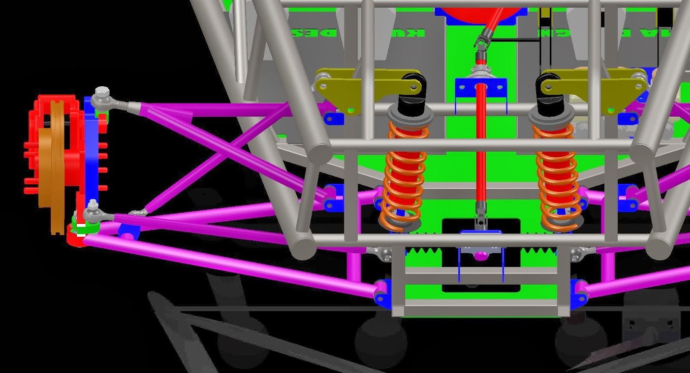
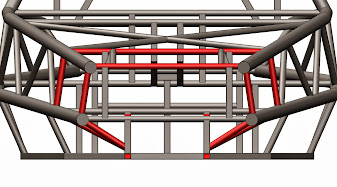
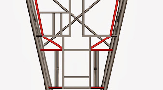
Be that as it may, I did wrestle with the idea of further support similar to Horizon Job's suggestion but decided against due to excessive overbuild. I suppose it's better to err on the side of caution in these matters and easy enough to rectify. I added tubes (red) as suggested, all of which should be carrying the suspension loads into the side spars. I will probably replace the tubes in favor of .125" steel plate as the loads should be tension.
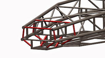
The free body diagram I come up with to describe the pivot point of the bell crank results in minimal deflection of the top support tube as the forces are reacted through the lower support tube. Please let me know if you think otherwise
The rear is a bit more of a cluster admittedly. I'm am seriously considering drastic cutting and redesign if I can't reasonably strengthen the rear suspension pickups in an elegant manner.
Quote:
I'm undecided about the center two beams, I'm assuming that you will be adding some more to the chassis (tunnel and such) but to my dilettante eyes it seems that the two boxes should be connected a bit better to reduce flex.
Horizenjob beat me to the rest

I assume by boxes you mean front and rear suspension boxes?? I wasn't planning on running a center tunnel as the thought was to maintain the loads through the 4 main spars but that would of course necessitate further connection between the suspension pickup and the side spars. See above.
Quote:
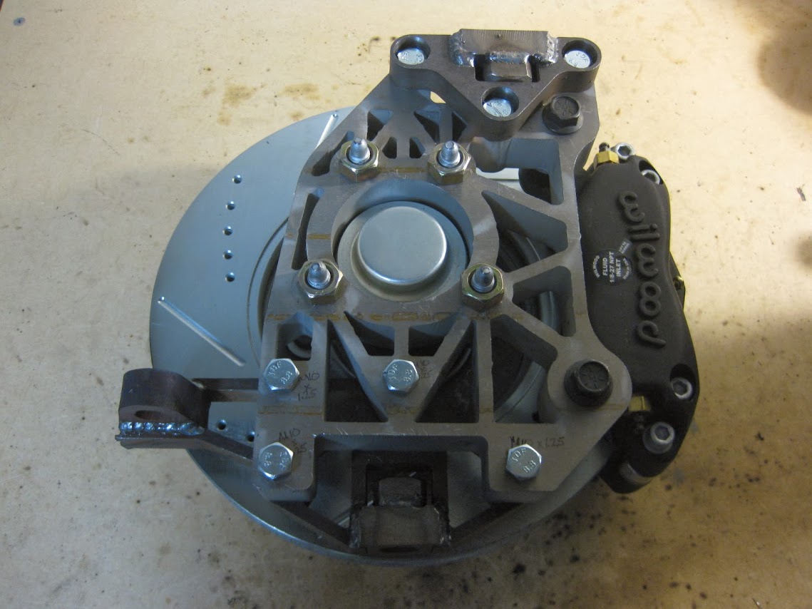
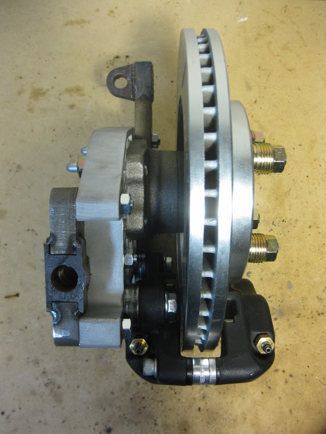
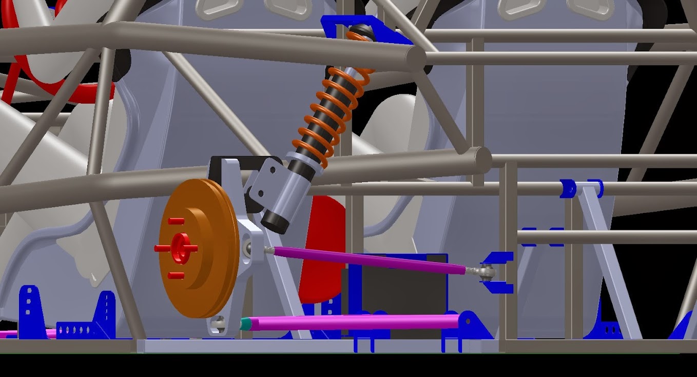
Something was bothering me about the spindles. ..
I'd like to have seen material where I filled in with red. The two yellow lines display the edges of the load supporting area you have, the black line shows the actual amount of cross section.
That's a rather heavily loaded node. .. Spring loads, steering loads, brake load, instantaneous shock loads, etc.
I performed a FEA analysis of this simplified assembly with a my estimated front corner loads at a 10g bump and was well within 5+ factors of safety. Adding more radius certainly would help with stress concentrations which is always a good thing! It's 1" thick 7075 AL BTW.
Quote:
all those rectangles needing a diagonal when trapisoides could have been used.
Like this?
Quote:
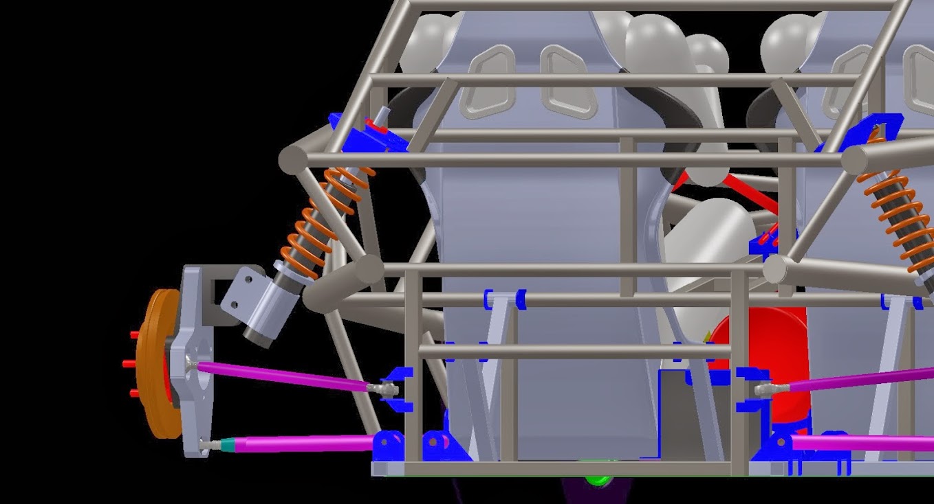
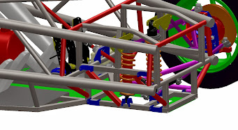
after that put some diagonals in the area of the LCA pickup points in a horizontal plane to stop it "walking" around under braking.
Like this (looking from the bottom, car forward to the bottom of the pic)?
Quote:
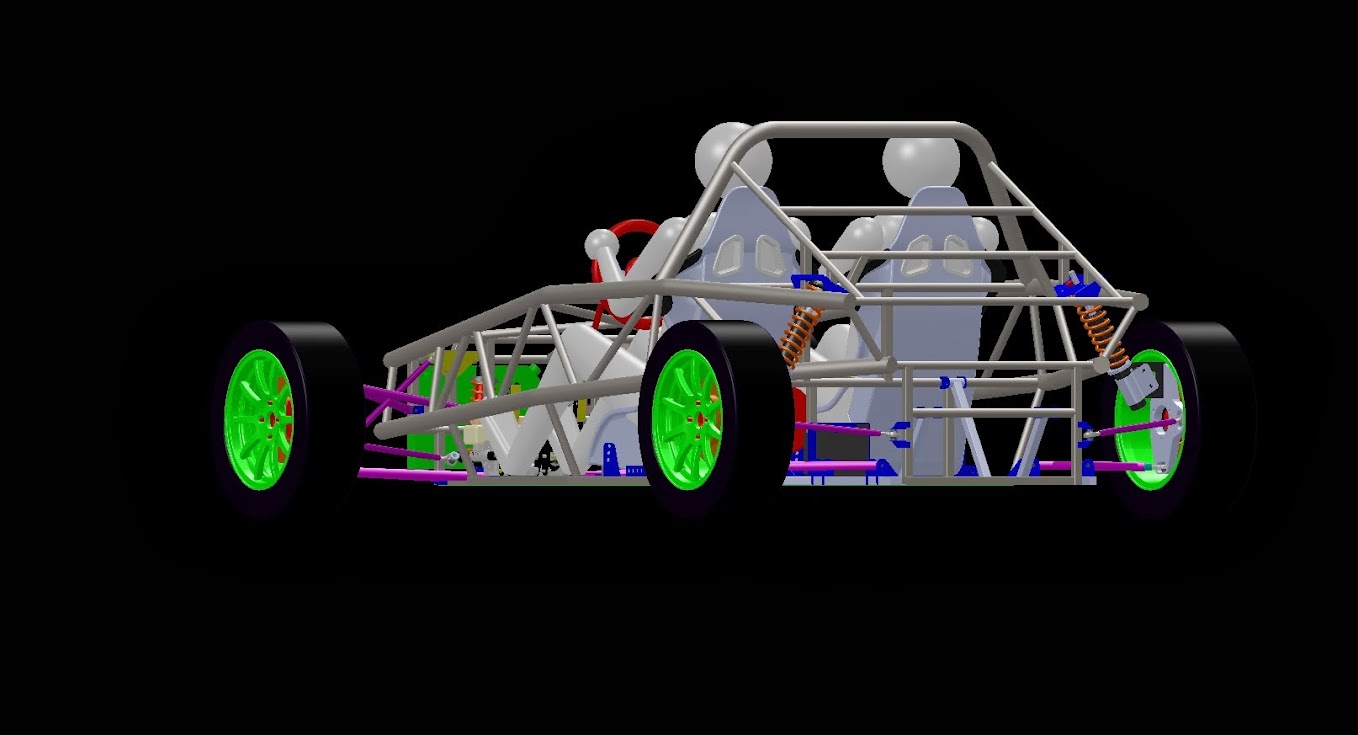
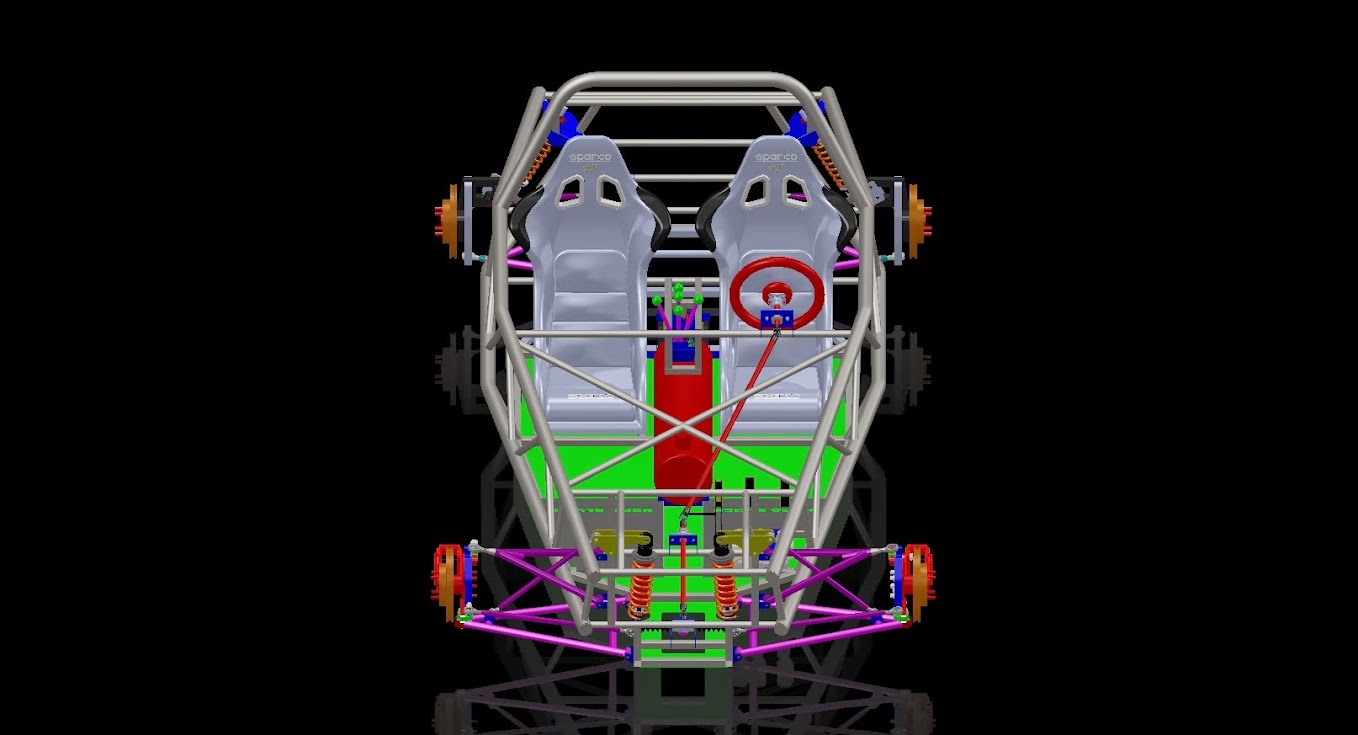
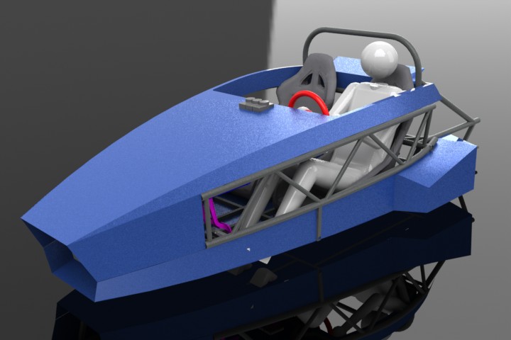
Either the scale of the seats is off or that of the "passengers" - or are they supposed to be 7' tall?
Ha, yea. I'm 6'5" so those dummies represent me. I measured all my appendages and resized each joint in the model accordingly so it should be pretty accurate.