LocostUSA.com

Learning how to build Lotus Seven replicas...together!
It is currently April 17, 2024, 10:20 pm

All times are UTC - 5 hours [ DST ]


Post new topic Reply to topic  [ 31 posts ]  Go to page Previous  1, 2, 3  Next
Author Message
PostPosted: March 28, 2014, 4:38 pm 
Offline
User avatar

Joined: July 27, 2013, 3:16 pm
Posts: 336
Location: Cedar City UT
hmmmmm....

looking at the pics of this `53 resto/hotrod made me think (what is sometimes a bad thing :roll: )

Image
Image
more details here; http://www.jalopyjournal.com/forum/showthread.php?t=629357&showall=1

i do have aluminum front and rear craddles that let me drop the drivetrain if there is need for major engine or transaxle work ...

Image

... so it does not make sense (from a weight standpoint) to build a traditional ladder frame with a removable cab and bed on top of it.

what do you guys think about making the cab/bed an integral part of the frame with just the front/rear fenders and the hood removable ?!?

this would save a lot of weight, mainly in the center tunnel ;
there is no need for covering the structural center tunnel with additional sheetmetal in the cab
same goes for the rocker panels (they are probably rusty anyway) ;
the rectangular tubing of the frame could replace the rocker panels
etc ...

_________________
- Stephan - Image


Top
 Profile  
Reply with quote  
PostPosted: March 29, 2014, 12:22 pm 
Offline
User avatar

Joined: July 27, 2013, 3:16 pm
Posts: 336
Location: Cedar City UT
a picture is slowly forming in my head :o ...

there is a lot of chassis engineering awesomeness in the new C7 Vette 8) ;

Image

notice the removable center tunnel "stiffener" plate that turns the open U into a torsional stiffer closed box-tube ...
that is definitely a detail that i`m going to shamelessly copy (and probably the susp subframe braces as well)

i think i will re-use the factory frame cutoff "stubs" (black) that will arrive with the drivetrain ...
Image

.. and tie them together with a formed steel plate center tunnel and two large (thin wall) box tubing sections that will replace the rocker sheetmetal panel of the stock cab.
for safety sake (and to have a strong mounting point for modern 3-point belts) i`m thinking to add a 1.75 x .120 DOM rollbar to the cab
(i personally would even add an A-pillar rollbar loop)
the rollbar could tie direct into the box tube rockers and also support the back wall so that i can weld the bed sides to it.
additionally i`m thinking to add underdash "spreader" bars that would tie the door hinge/A-pillar uprights to each other and to the center tunnel & firewall
(and ultimately into the front frame stubs)
this will also give me a strong point for hanging the pedal box and steering column (and greatly reduce cowl shake)

basically i`m thinking to turn the old "cab on frame" truck into a "unibody with subframe"

... just thinking out loud :roll: ....
any suggestions are very welcome :cheers:

_________________
- Stephan - Image


Top
 Profile  
Reply with quote  
PostPosted: March 30, 2014, 8:54 am 
Offline
User avatar

Joined: September 22, 2005, 8:12 am
Posts: 1880
Location: 4AGE in S.E. Michigan
Stephan
Look at both the Vette and Viper center tunnel designs and the sectional width and height used. The close out plate on the Vette tunnel, if I recall increased the torisional resistance by more then 10% for the ZO6 chassis. Big time improvement. But aligning all the small bolt holes was a PITA. The front ditch joint would tend to spread, but with a steal fire wall you should have less of a problem. I would suggest a couple small tube "X" braces bolted across the bottom of the tunnel, since you will have a lot more ground clearance. I do not think the 1950's box will carry the uni-body loads. Several of these type builds use the S-10 chassis. Dave W


Top
 Profile  
Reply with quote  
PostPosted: March 30, 2014, 11:20 am 
Offline
The voice of reason
User avatar

Joined: January 10, 2008, 4:47 pm
Posts: 7652
Location: Massachusetts
Quote:
truck is ~116" wb ... Corvette is ~106"
what would you do?


There's a lot of work doing a classy job on a project like this. So looking at your C6 chassis it seems the best place to add 10 inches is in the cylinder region. Make a U shaped cut around both chassis engines. Then saw a V4 off one engine and weld it onto the other one and tidy up. With a big job like this you should "offer" the V4 part a couple of times before you actually weld it.

At this point you can just drag the truck body around behind you. It'll probably still carry stuff fine too.

_________________
Marcus Barrow - Car9 an open design community supported sports car for home builders!
SketchUp collection for LocostUSA: "Dream it, Build it, Drive it!"
Car9 Roadster information - models, drawings, resources etc.


Top
 Profile  
Reply with quote  
PostPosted: March 30, 2014, 12:35 pm 
Offline
User avatar

Joined: July 27, 2013, 3:16 pm
Posts: 336
Location: Cedar City UT
horizenjob wrote:
Quote:
truck is ~116" wb ... Corvette is ~106"
what would you do?


There's a lot of work doing a classy job on a project like this. So looking at your C6 chassis it seems the best place to add 10 inches is in the cylinder region. Make a U shaped cut around both chassis engines. Then saw a V4 off one engine and weld it onto the other one and tidy up. With a big job like this you should "offer" the V4 part a couple of times before you actually weld it.

At this point you can just drag the truck body around behind you. It'll probably still carry stuff fine too.


wut? :shock:

i think i lost you somewhere between U-cut and V4 :lol:

but actually your right that adding wb could be done in front of the cylinders by sliding the engine (with torque tube & transaxle) back a couple inches
but then it will probably create a footbox space issue :roll:
nah... i think i leave the drivetrain as it is :wink:

_________________
- Stephan - Image


Top
 Profile  
Reply with quote  
PostPosted: April 7, 2014, 3:26 pm 
Offline

Joined: October 28, 2012, 6:21 pm
Posts: 37
Location: 10 square miles surrounded by reality.
Was watching the show Roadkill on youtube. If you have not seen it I would totally recommend you watch them. In the latest episode they have a segment where they talked about a guy who specialized in custom autocross trucks. His name is Rob MacGregor and he is the owner of No Limit Engineering. Looking him up on google showed some good ideas on a frame, heck you can buy one of his for 12,000 ;)

_________________
Brian


Top
 Profile  
Reply with quote  
PostPosted: April 7, 2014, 8:48 pm 
Offline
User avatar

Joined: July 27, 2013, 3:16 pm
Posts: 336
Location: Cedar City UT
Brian
thanks for the headsup ...
but no thanks :P
if you add up all the options like brakes, coilovers, and and .............. your looking at probably ~$20k for just the chassis
and then its still a imho grossly outdated design with solid rear end and all :ack:

FYI the rolling C6 drivetrain as pictured was "only" $8550 ... and this includes engine and transmission :wink:
considering all the nice parts you get with it i would call it a real bargain.

_________________
- Stephan - Image


Last edited by RoosterBooster on April 11, 2014, 6:27 pm, edited 1 time in total.

Top
 Profile  
Reply with quote  
PostPosted: April 11, 2014, 6:26 pm 
Offline
User avatar

Joined: July 27, 2013, 3:16 pm
Posts: 336
Location: Cedar City UT
the project officially started : :D

Image

yesterday my friend Ryan dropped off the Vette drivetrain crates and the truck...

Image

... as well as an insane heavy 3/4" thick steel plate that i will use as a fab surface plate/welding table

Image

Ryan and me feeling like kids on Christmas day :cheers:

Image

now i just need to reassemble the drivetrain and then i can start with taking measurements & the CAD drawings

Image

Cleveland pick-a-part did a outstanding job wrapping and crating everything
... nice to see a business that cares that you get your stuff undamaged 8)

btw
GM made us a gift: the front subframe crate is already machined and drilled for two engine/ wb positions :smokin:
the stock 105.7" wb Vette and a 107" wb position that is off-set to the passenger side by .75"
what is just about perfect for the truck ! ... thank you GM :P

the not so nice thing was that i wanted to quickly remove the composite leaf for easier frame setup
(and that i can cycle the suspension to check for clearance)
... needed over 2 hours and complete disassembly of the front suspension to get that darn pre-loaded B%@# out of there :ack:

_________________
- Stephan - Image


Top
 Profile  
Reply with quote  
PostPosted: April 14, 2014, 11:19 am 
Offline
User avatar

Joined: July 27, 2013, 3:16 pm
Posts: 336
Location: Cedar City UT
was busy;
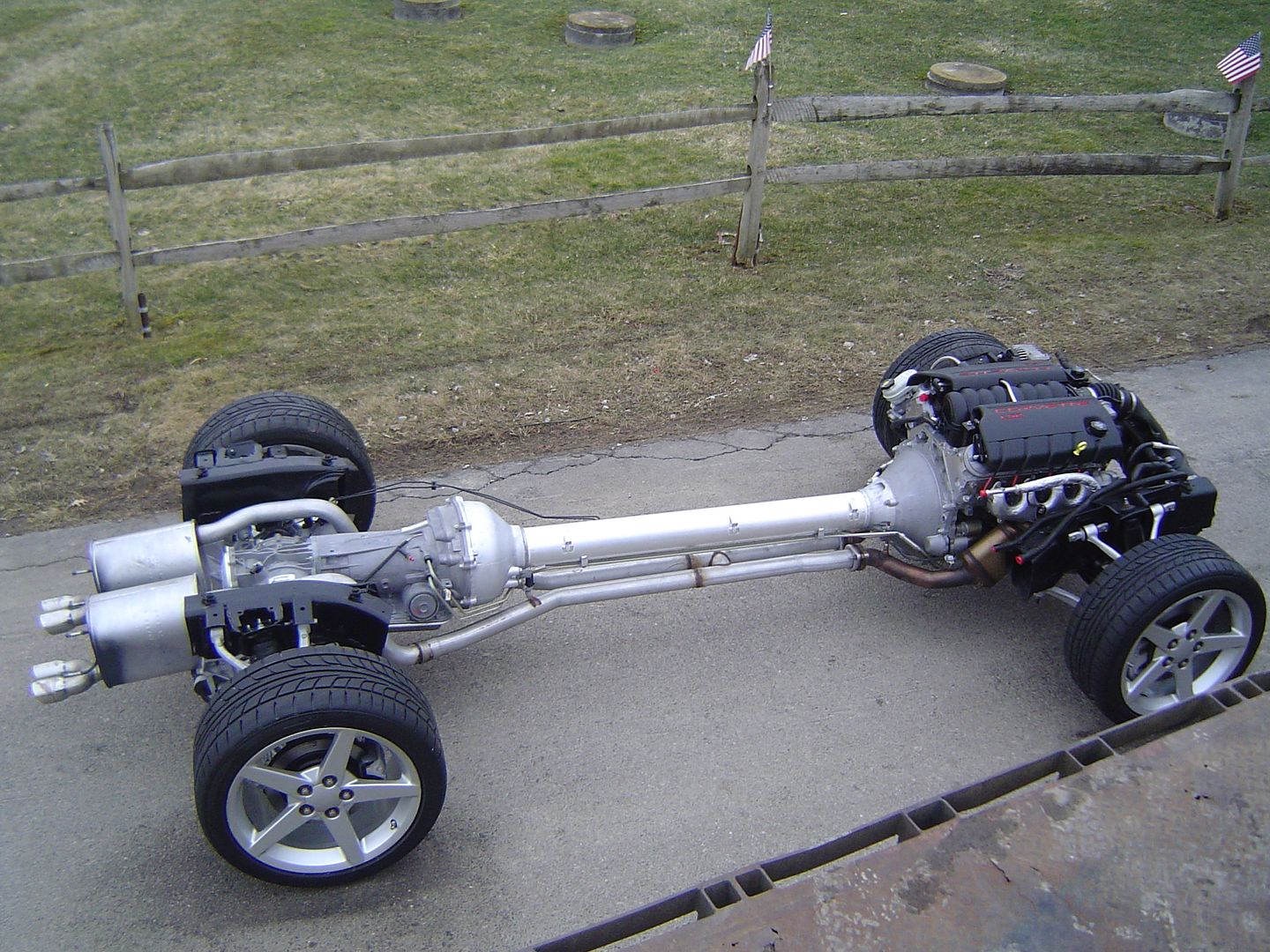
stripped & capped everything on the engine that i dont need for fabbing and re-assembled the rolling drivetrain

Image

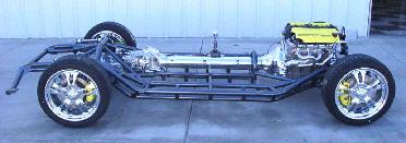
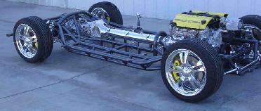
notice how far the engine is set back by using the "long WB" mounting holes
i`m used to wrench on taller things so it is kinda strange to see this extremely low slung drivetrain sitting at ride height for the first time...

Image

my bro`s reaction; "its a frigging skateboard with a V8 !!! "

Image

the 3/4" engine off-set to the passenger side is giving me more clearance for the steering shaft
and it will probably also give me a little more room for the driver footbox

Image

i discovered that there are two common machined planes at the front and rear subframe,
so i drilled two 2x2x.125" tubing sections to bolt them together
the two tubes will later sit on the big steel surface plate
this shoul bring the two clips to the same level
with diagonal measuring and a rotary laser i should be able to square the clips to near factory specs

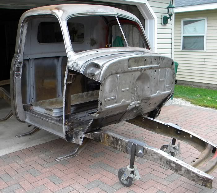
after some measuring and thinkering with the chassis i decided to scrap the 'large box tube' idea.
i have more room under the cab then what i expected so i`m going with a tubular space frame instead
something similar to this sriiimotorsports chassis ;
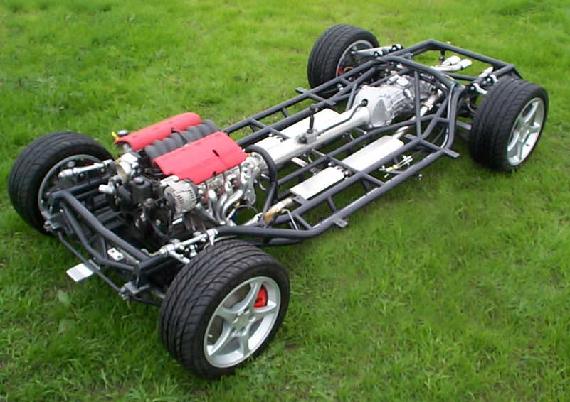
Image

Image

Image

found the pics at SRIII Motorsports Inc.

round tube gives me a lot more freedom in shaping the frame tightly around the drivetrain

the factory frame cutoffs have a .75" id corner radius, so i`m going to use 1.5" DOM tubing
this allows me to blend the cutoffs clean & nicely into the space frame.

_________________
- Stephan - Image


Top
 Profile  
Reply with quote  
PostPosted: April 14, 2014, 9:42 pm 
Offline

Joined: October 19, 2009, 9:36 pm
Posts: 2199
Location: meadview arizona
Stephan,

you keep adding at the end of your posts a line about comments, clearly you are in no need of any thus far in the build, although i will be keeping my eye on you from a far, just in case.

you know exactly where you are going on this build.

when you used the alternative engine holes that set the motor sideways as well as back, has this affected the alignment of the front and back cradles?

its a pitty that you can't move the diff forward in the rear cradle to solve your wheel base problem, in fact, can you just mount the cradle to your new chassis for the suspension and mount the diff directly to the chassis in a more forward location, having your drive shafts angled backwards to the wheels, you are obviously conversant with steep CV angles.

_________________
this story shall the good man teach his son,
and chrispin chrispian shall ne'er go by,
from this day to the end of the world.
but we in it shall be remembered.


Top
 Profile  
Reply with quote  
PostPosted: April 14, 2014, 10:20 pm 
Offline
Toyotaphobe
User avatar

Joined: April 5, 2008, 2:25 am
Posts: 4829
Location: Fort Worth, Texas
How about a simple structure to mount the front cradle forward the other 3" or so you need to match the wheelbase?

That is if the engine and firewall can coexist that way.

Better weight distribution that way too.

_________________
mobilito ergo sum
I drive therefore I am

I can explain it to you,
but I can't understand it for you.


Top
 Profile  
Reply with quote  
PostPosted: May 18, 2014, 11:41 am 
Offline
User avatar

Joined: July 27, 2013, 3:16 pm
Posts: 336
Location: Cedar City UT
John
using the off-set engine mounting holes puts the complete drivetrain on a slight angle...
but it is only a very small degree of miss-alignment at the rear CV`s

i noticed that the rear axle shafts pointed slightly forward,
so i removed the rear cradle and machined the transaxle mounting holes to slide the cradle back by 3/4"

Image

Image

its only a small increase in WB... but may as well do whatever is easy to do

after i had the cradles bolted down and squared/aligned i started bending the lower tubes...

Image

needed 3 bends each tube to squeeze them tightly around the fuel tanks and so that they still fit under the cab/sidesteps

Image

with the upper tubes in place i started with the cross-over connetions;

Image

Image

most of the X-bracing in place;

Image

Image

started boxing-in the tube to frame cutoff connections;

Image

Image

today is shop cleanup day ... should be able to start fitting the cab onto the frame sometimes next week ;)

_________________
- Stephan - Image


Top
 Profile  
Reply with quote  
PostPosted: May 19, 2014, 10:50 am 
Offline
User avatar

Joined: July 27, 2013, 3:16 pm
Posts: 336
Location: Cedar City UT
finish welded the main frame, bolted the cradles back on
and rolled the whole thing out onto the street for some pics;

Image

the frame looked large on the welding table,
but down on the ground it is very low profile

Image

Image

Image

Image

Image

Image

now i need to take the body apart so that i can start fitting the cab
cant wait to see how it will look :mrgreen:

_________________
- Stephan - Image


Top
 Profile  
Reply with quote  
PostPosted: May 19, 2014, 11:15 am 
Offline
User avatar

Joined: April 12, 2012, 11:56 am
Posts: 662
Location: Pemberton, BC
Wow Stephan. That is just amazing.
What do you do for the afternoon. Take a little snooze? :twisted:

_________________
Martin


My build log:
viewtopic.php?f=35&t=14520&start=0
My build video:
https://vimeo.com/143524140 password "matovid"


Top
 Profile  
Reply with quote  
PostPosted: May 29, 2014, 6:38 pm 
Offline

Joined: May 29, 2014, 6:24 pm
Posts: 1
G'day Stephen,

Firstly Wow what a great project you are creating, have loved ever picture and txt you have posted. Please please keep them coming.

I have just commenced the same build, here in Brisbane Ausralia, only difference, is i'm using the Cadillac rolling drive train from an XLR-V (2009) and my truck is a 1950.

I was very excited to see you are using the frame cutoff's, and am desperate to do the same (along with using my existing original 3100 chassis, however as you will see from the photo my drivetrain has not come with these cutoff's. I've search high and low and can't find a set anywhere (any chance you would know where is could get my hands on them ?

Looking forward to the next instalment :)

Cheers mate.
Shaun


You do not have the required permissions to view the files attached to this post.


Top
 Profile  
Reply with quote  
Display posts from previous:  Sort by  
Post new topic Reply to topic  [ 31 posts ]  Go to page Previous  1, 2, 3  Next

All times are UTC - 5 hours [ DST ]


Who is online

Users browsing this forum: No registered users and 12 guests


You cannot post new topics in this forum
You cannot reply to topics in this forum
You cannot edit your posts in this forum
You cannot delete your posts in this forum
You cannot post attachments in this forum

Jump to:  
POWERED_BY