LocostUSA.com

Learning how to build Lotus Seven replicas...together!
It is currently April 18, 2024, 11:08 pm

All times are UTC - 5 hours [ DST ]


Post new topic Reply to topic  [ 2911 posts ]  Go to page Previous  1 ... 176, 177, 178, 179, 180, 181, 182 ... 195  Next
Author Message
PostPosted: March 14, 2023, 8:37 pm 
Offline
User avatar

Joined: October 24, 2008, 2:13 pm
Posts: 5326
Location: Carlsbad, California, USA
@KB58

Thanks for that tip, Kurt.

When I finished up the boot structure welding, I did take a strong, narrow, Harbor Freight LED light and look at every welded joint from the forward attachments of the trailing arms (they were part of the known, unfinished welds I'd marked with tape and a Sharpie) to the boot hoops. I can now say with confidence everything is welded in that area. Some are not pretty, but they're solid welds.

You are right, I plan to do the same process all over the chassis. I still have welds to do at the front of the chassis for the coilovers and maybe a strengthening gusset behind the chassis rail they mount to as well.

Embarrassingly, there was a pinhole void in one of the LCA welds I just posted yesterday. I thought I had corrected all those. :BH: I'll fix it though.

The thought of powder coating the chassis hadn't ever crossed my mind, Kurt. I assumed that would cost a fortune. They would have to chemical bath my chassis now to get the primer, paint and joint sealer off before doing so. I'm not sure what other prep work they might have to do first.

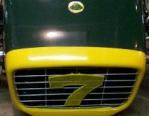
However, there are smaller parts I should look into like the spare tire carrier, which bolts on at the back. That would be worth doing if it's affordable. Thanks for that info on the Vista company.
Attachment:
Spare Tire Carrier.jpg


Cheers,


You do not have the required permissions to view the files attached to this post.

_________________
Damn! That front slip angle is way too large and the Ackerman is just a muddle.

Build Log: viewtopic.php?f=35&t=5886


Top
 Profile  
Reply with quote  
PostPosted: March 14, 2023, 9:08 pm 
Offline
Mid-Engined Maniac

Joined: April 23, 2006, 8:26 pm
Posts: 6419
Location: SoCal
No chemicals, they media (or sand?) blast it as standard practice, so rust or paint isn't a concern. I don't remember exactly what they charged, but it was a long time ago for both so I'm sure it's more, but it was on the order of $400-500 maybe. Easy to ask, just say you have a "dune buggy" frame and see what they'd want. They do those all the time. Oh, and it's well worth having everything done at once, because a handful of small parts adds very little work for them if part of a bigger deal, but will be $$$ if done separate.

_________________
Midlana book: Build this mid-engine Locost!, http://midlana.com/stuff/book/
Kimini book: Designing mid-engine cars using FWD drivetrains
Both available from https://www.lulu.com/


Top
 Profile  
Reply with quote  
PostPosted: March 16, 2023, 9:36 am 
Offline
Automotive Encyclopedia
User avatar

Joined: December 22, 2006, 2:05 pm
Posts: 8044
You could fit a tube and stud to the bolt-on tire carrier, then use a locking lug nut to secure the spare and a traditional leather belt or no top wrap at all.

_________________
Miata UBJ: ES-2074R('70s maz pickup)
Ford IFS viewtopic.php?f=5&t=13225&p=134742
Simple Spring select viewtopic.php?f=5&t=11815
LxWxHt
360LA 442E: 134.5x46x15
Lotus7:115x39x7.25
Tiger Avon:114x40x13.3-12.6
Champion/Book:114x42x11
Gibbs/Haynes:122x42x14
VoDou:113x44x14
McSorley 442:122x46x14
Collins 241:127x46x12


Top
 Profile  
Reply with quote  
PostPosted: March 16, 2023, 10:08 pm 
Offline
User avatar

Joined: October 24, 2008, 2:13 pm
Posts: 5326
Location: Carlsbad, California, USA
@MV8
I have the traditional leather belt you suggested already done and some really cool western saddle hardware & buckles to cinch and fasten it. They're done by a guy here in California named Jeremiah Watt. If I can find someone who can tool the leather strap for me, I'll likely do that too.

I've settled on a Western theme for the car since it's based on a Mustang donor. I've saved some of the Mustang donor's badging and will try to use it on the car as well.

The locking hoop is already done. It was pretty simple to do and I kind of like it. It's different. I'm going for the "Character Award" if nothing else [SMILE].

Cheers,
Attachment:
Belt 1.jpg

Attachment:
Belt 5.jpg

Attachment:
Belt 8.jpg

Attachment:
Belt 10.jpg

Attachment:
Locking hoop.jpg


You do not have the required permissions to view the files attached to this post.

_________________
Damn! That front slip angle is way too large and the Ackerman is just a muddle.

Build Log: viewtopic.php?f=35&t=5886


Top
 Profile  
Reply with quote  
PostPosted: March 17, 2023, 10:06 pm 
Offline
User avatar

Joined: October 24, 2008, 2:13 pm
Posts: 5326
Location: Carlsbad, California, USA
One little hiccup with mounting the coilovers to the LCA (Lower Control Arms) showed up, but I think I have a solution. Let me know if you see a better one, or see something risky with mine. I'll use the photo below to illustrate.
Attachment:
Shear Pin Solution.jpg

The bolt you see inserted in the coilover bracket is the largest one I can fit due to interference with the two LCA tubes. Clearly, there isn't enough thread length for safely securing the bolt.

The bolt head is 5/16". If I machine a pin from mild steel and make the head width 1/16", then I should have enough room to drill a hole near its end for a shear pin (plus maybe a thin washer?). I have some high quality SAE shear pins (one in photo) that I got from McMaster-Carr on hand. It takes a lot to move them once installed (typically a pin punch & hammer) if you drill the correct hole size. That should provide enough safety from the pin coming free.

What do you think?

Cheers,


You do not have the required permissions to view the files attached to this post.

_________________
Damn! That front slip angle is way too large and the Ackerman is just a muddle.

Build Log: viewtopic.php?f=35&t=5886


Top
 Profile  
Reply with quote  
PostPosted: March 18, 2023, 6:50 am 
Offline
User avatar

Joined: September 22, 2005, 8:12 am
Posts: 1880
Location: 4AGE in S.E. Michigan
First the shock bushing has a sleeve between the rubber bushing. That sleeve needs to be in contact with the bracket sides, via tightening down the bolt. [if not the holes will be distorted in no time] Replace the cap screw with an Allen button head screw. Next use threaded tube stock or a nut, then drill out the RH bracket hole to a larger size that matches the tube or nut, and weld in the nut or tube to the bracket. Align the tube or nut with the bolt, before welding. You should have 1 diameter thread engagement as a very min and 1 1/2 diameters are much better. Hardware suppliers do make specialty nuts with a pilot or shoulder, but finding one would probably be a PITA. If you know someone with a lathe would be the best option.


Top
 Profile  
Reply with quote  
PostPosted: March 18, 2023, 8:03 am 
Offline

Joined: August 28, 2010, 7:53 am
Posts: 343
On the LCA bolt, you could machine a threaded sleeve that uses a short bolt from each size.
You don't want the threads in sheer, so the sleeve needs to span the bracket.
You could use 1/4 or 5/16 bolts with mil spec washers.
I could draw a pic, if im not making sense. I have a lathe, if you need someone to make them.....


Top
 Profile  
Reply with quote  
PostPosted: March 18, 2023, 8:50 am 
Offline
Automotive Encyclopedia
User avatar

Joined: December 22, 2006, 2:05 pm
Posts: 8044
Since I know you don't want to cut it off, I also suggest a coated/plated/painted allen socket head bolt with a zinc plate grade 5 nut and washers on both ends. The washer under the head will need to be a tight fit to the shank since the socket head shoulder is so much smaller. Grade 8 would be a closer match to the socket bolt strength but it isn't necessary. Black oxide coating might as well be bare metal. Looks to be 3/8" shank.

Echoing that a pin is not going to work long.

I'd cut it off and make bigger flanges to bring the eye up and out if there is room but it isn't necessary. I'm sure the socket cap screws will work and Sean's recommendation could work too.

_________________
Miata UBJ: ES-2074R('70s maz pickup)
Ford IFS viewtopic.php?f=5&t=13225&p=134742
Simple Spring select viewtopic.php?f=5&t=11815
LxWxHt
360LA 442E: 134.5x46x15
Lotus7:115x39x7.25
Tiger Avon:114x40x13.3-12.6
Champion/Book:114x42x11
Gibbs/Haynes:122x42x14
VoDou:113x44x14
McSorley 442:122x46x14
Collins 241:127x46x12


Top
 Profile  
Reply with quote  
PostPosted: March 18, 2023, 7:53 pm 
Offline
User avatar

Joined: October 24, 2008, 2:13 pm
Posts: 5326
Location: Carlsbad, California, USA
@davew
@Sean in CT
@MV8

Gentlemen,

Thank you so much for your ideas. My next door neighbor had an emergency situation that required my help today. I didn't get a chance to digest your posts, or get out in the garage today at all. However, I did want to acknowledge your posts tonight and thank you.

Best,

Lonnie

_________________
Damn! That front slip angle is way too large and the Ackerman is just a muddle.

Build Log: viewtopic.php?f=35&t=5886


Top
 Profile  
Reply with quote  
PostPosted: March 19, 2023, 2:38 pm 
Offline
User avatar

Joined: October 24, 2008, 2:13 pm
Posts: 5326
Location: Carlsbad, California, USA
Thanks again, gents.

I'm going to poke around on McMaster-Carr to see if they have something read made such as the shoulder bolt mentioned. I do have a little Harbour Freight mini-lathe. It's painfully slow on mild steel or stainless, but I can get the job done even if it's totally boring to do so. :ack:

The idea of a 1/2" cylinder spanning the bracket outside-to-outside, threaded all the way through as 5/16" sounds good. With two good bolts butting up to washers on either end & the use of a thread locker, it should provide the needed "squeeze" and safety too.

I should have dry lab'ed the bolt/bracket situation by clamping the bracket in place before welding then trying a bolt. If I would have turned the bracket around the other way, there would be no problem. There would be enough clearance for a longer bolt. I was trying to get the coilover mount as close to the end of the LCA as possible to minimize the motion ratio. This is a street car, so things are not all that critical. Me dumb.

Cheers,

_________________
Damn! That front slip angle is way too large and the Ackerman is just a muddle.

Build Log: viewtopic.php?f=35&t=5886


Top
 Profile  
Reply with quote  
PostPosted: March 19, 2023, 6:06 pm 
Offline

Joined: August 28, 2010, 7:53 am
Posts: 343
Lonnie I can make it for you from some mild steel. I have a 13" south bend that makes quick work of that sort of thing.....just make a diagram with dimensions.


Top
 Profile  
Reply with quote  
PostPosted: March 19, 2023, 11:02 pm 
Offline
User avatar

Joined: October 24, 2008, 2:13 pm
Posts: 5326
Location: Carlsbad, California, USA
@Sean in CT

Thank you for that kind offer, Sean. I may take you up on that.

Perry called tonight with another suggestion regarding removing the welded in bracket. I'm going to consider it too.

Frustratingly, our latest "atmospheric river" storm arrived a half day early this afternoon. It's scheduled to rain through midday on Thursday now. I'll have a lot of time to think over all the possibilities. If this keeps up, I may switch over to building an ark instead of a Locost. :BH:

Cheers,

_________________
Damn! That front slip angle is way too large and the Ackerman is just a muddle.

Build Log: viewtopic.php?f=35&t=5886


Top
 Profile  
Reply with quote  
PostPosted: March 22, 2023, 11:05 am 
Offline
User avatar

Joined: October 24, 2008, 2:13 pm
Posts: 5326
Location: Carlsbad, California, USA
@davew

This won't be news to you, Dave, but I found a nice tutorial on YouTube that has the information you mentioned plus some more. It's a nice, clarifying little tutorial for those of with less experience with these bushing setups. It's right here on YouTube.

Cheers,

_________________
Damn! That front slip angle is way too large and the Ackerman is just a muddle.

Build Log: viewtopic.php?f=35&t=5886


Top
 Profile  
Reply with quote  
PostPosted: April 2, 2023, 7:46 pm 
Offline
User avatar

Joined: October 24, 2008, 2:13 pm
Posts: 5326
Location: Carlsbad, California, USA
There's some good news: my lower control arm welds are much tougher than I ever expected. And, there's some bad news: my lower control arm welds are much tougher than I ever expected.

After thinking about it for several days, I took Perry's (MV8 implied one too) suggestion to cut off the troublesome brackets. I bought an arbor for my electric die grinder and some small, thin abrasive cutoff disks. Perry told me his technique for cutting through such welds, and I did my best to follow through on his successful method. What I'm finding is my weld penetration is much better than I expected. Those mothers are really on there. I'm supremely confident they would not have failed in service.

The trouble is they just don't want to come off now that I need them to do so. After 3 hours fiddling, I was getting so frustrated with the task that I quit for the day. To borrow from an old religious phrase: act in haste, repent at leisure. So, I stopped work intending to resume tomorrow with a fresh mind and better attitude. Here's where I am:
Attachment:
DSC06259.JPG


The welds are pretty well undercut, but are surprisingly deep into the meat of the bracket from the edges.
Attachment:
DSC06253.JPG

Attachment:
DSC06254.JPG

Attachment:
DSC06258.JPG


I'll get back at it in the morning. I'm obviously committed now. I'll have to just stick with it until the job gets done.

Cheers,


You do not have the required permissions to view the files attached to this post.

_________________
Damn! That front slip angle is way too large and the Ackerman is just a muddle.

Build Log: viewtopic.php?f=35&t=5886


Top
 Profile  
Reply with quote  
PostPosted: April 2, 2023, 8:31 pm 
Offline
Automotive Encyclopedia
User avatar

Joined: December 22, 2006, 2:05 pm
Posts: 8044
A Milwaukee angle grinder makes quick work of that. You'd just spread the flanges then put the grinder wheel down at the inside corner of the flange, grinding down to the base. Wear a dust mask, eye shield, and hearing protection. Don't breathe in the dust from the grinder wheel or cutoff discs.

The cutoff discs are much better for thin materials and detail work. The discs could have been used to cut just the flanges out then new wider, longer, notched flanges fitted over the still welded base and bolted together with a spacer to help hold them in the perfect position and width for welding. Quick and easy.

However at this point, it looks like you are almost there.

Use the angle grinder to clean up the plate surface after.

_________________
Miata UBJ: ES-2074R('70s maz pickup)
Ford IFS viewtopic.php?f=5&t=13225&p=134742
Simple Spring select viewtopic.php?f=5&t=11815
LxWxHt
360LA 442E: 134.5x46x15
Lotus7:115x39x7.25
Tiger Avon:114x40x13.3-12.6
Champion/Book:114x42x11
Gibbs/Haynes:122x42x14
VoDou:113x44x14
McSorley 442:122x46x14
Collins 241:127x46x12


Top
 Profile  
Reply with quote  
Display posts from previous:  Sort by  
Post new topic Reply to topic  [ 2911 posts ]  Go to page Previous  1 ... 176, 177, 178, 179, 180, 181, 182 ... 195  Next

All times are UTC - 5 hours [ DST ]


Who is online

Users browsing this forum: No registered users and 52 guests


You cannot post new topics in this forum
You cannot reply to topics in this forum
You cannot edit your posts in this forum
You cannot delete your posts in this forum
You cannot post attachments in this forum

Jump to:  
POWERED_BY