LocostUSA.com

Learning how to build Lotus Seven replicas...together!
It is currently April 18, 2024, 2:12 am

All times are UTC - 5 hours [ DST ]


Post new topic Reply to topic  [ 57 posts ]  Go to page Previous  1, 2, 3, 4
Author Message
PostPosted: September 19, 2011, 9:28 am 
Offline

Joined: February 17, 2010, 1:48 pm
Posts: 364
Location: Seattle, Wa
looking good!!! The reverse set-up looks top notch!

one note - the control arm cut-outs in the body look a little small...not sure if it's just a difference between out kits, but I recall having to enlarge my cut-outs to account for full-suspension droop and compression.

_________________
Building a MNR Vortx w/ '99 Miata donor: viewtopic.php?f=35&t=9631


Top
 Profile  
Reply with quote  
PostPosted: September 25, 2011, 6:41 pm 
Offline
User avatar

Joined: May 16, 2010, 7:18 pm
Posts: 39
Location: Rochester, NY
first350 wrote:
one note - the control arm cut-outs in the body look a little small...not sure if it's just a difference between out kits, but I recall having to enlarge my cut-outs to account for full-suspension droop and compression.


I have a feeling you could be correct. Seemed to clear my templates but I expect the real thing will sit a little further out from the chassis. Figured I can always take material off, but not add back on!
Hoping to get some time next week to get the body on and will see then.


Top
 Profile  
Reply with quote  
PostPosted: December 18, 2011, 9:22 pm 
Offline
User avatar

Joined: May 16, 2010, 7:18 pm
Posts: 39
Location: Rochester, NY
OK, been a long time since I posted. Have not had very much time on the car.

I have re-fitted the front end, had to open up some of the holes for fitment.
Attachment:
front1.jpg

Have also fitted rad, wired fan etc. I have coolant lines etc on order from MNR, and will fit when these arrive so I can do a first extended run.

Refitted driveshafts and rear end. MNR supplies some aluminum spacers for the rod ends and the build manual says to pack this out with many washers. Didnt like this so turned up my own aluminum spacers for a proper fit.
Attachment:
rear1.jpg

Also fitted handbrake and roughed in the cables. All good so far.
Attachment:
handbrake.jpg

I have also done a bit more body wiring, fitted the headlamps etc, but have been bad at taking pictures. Stuff I can do in short sessions in the garage. I'm hoping things free up soon so I can give it another burst of work and see some progress.


You do not have the required permissions to view the files attached to this post.


Top
 Profile  
Reply with quote  
PostPosted: March 4, 2012, 5:45 pm 
Offline
User avatar

Joined: May 16, 2010, 7:18 pm
Posts: 39
Location: Rochester, NY
I'm done with wiring. The only items left to wire are the rear lights.
I assembled a jaycar speedo corrector module, not as bad as it looks. The instructions are very easy to follow. It actually works!
Attachment:
Jaycar speedo kit.jpg

Attachment:
Jaycar kit assembled.jpg

After finding an enclosure it is just a matter of giving it a switched power input and then splicing into the speedo signal input from the bikes wiring loom. The unit is velcro'd up behind the dash in a place that I can get to later for calibration once on the road.

As per a previous post, I stripped out the standard bike relays for turn signals and replaced with a signal dynamics unit that allows push button input. So I've run a quick release mic cable to the steering wheel for turn signal pushbuttons on the wheel. While at it I also ran horn, headlamp flash / Hi beams (headlamps come on dipped once the ECU sees the engine is running, per the standard way the bike is wired), as well as engine kill and starter, all on the wheel. For main ignition on, I'm using a RFID reader in a hidden area. Not that I'll be leaving this in too many places, with the wheel off there is no obvious way to start the car.
Attachment:
steering wheel.jpg

In the above pic, buttons on wheel at left and right are for turn signals / 4 way flashers. On the 1mm carbon fiber plate are - lower left - main beams (button pushed to right), flash (push to left which is momentary). On lower right is engine kill and the red button is starter. Oh and I found a Yamaha tank decal that perfectly fit the horn button in the center.
In order to fit all the wiring in, I had to make an aluminum spacer approx 3/4" thick with a hollow center (not pictured).


You do not have the required permissions to view the files attached to this post.


Top
 Profile  
Reply with quote  
PostPosted: March 4, 2012, 6:12 pm 
Offline
User avatar

Joined: May 16, 2010, 7:18 pm
Posts: 39
Location: Rochester, NY
Cooling is done also. After looking at other posts and cooling diagrams, it seemed to me that putting the expansion tank on the scuttle like most people do would require excessively long lines.
I made a bracket that mounts the tank forward, just toward the rear of the nose.
Attachment:
coolant tank mounted.jpg

Top hose tees to the rad overflow and the thermostat bypass. Lower hose tees into the large lower radiator return that goes into the engine at the rear (as it sits in the car) close to the output shaft.
There is a small hose that also enters the engine at the output shaft. I made some hardline to pipe this carefully around the prop adapter to exit at the top, just forward of the shifter arm. This is connected to the cold start manifold (the other end of which is connected just as standard from a small pipe that exits the top of the block before the thermostat.
Top hose from thermostat goes to top of rad. Difficult to see is that there is a small hose from the bottom of the engine which is the hot water exit from the water-to-oil cooler (std on bike), which is teed into this top line so that it it cooled before returning. I've seen that many people just tee it in to the bottom hose and have no problem.
Attachment:
cooling 1.jpg

Attachment:
cooling 2.jpg


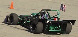
This is what it looks like with the nose finally mounted (hopefully for the final time).
Attachment:
engine bay with cooling..jpg


Scuttle is mounted, though I think I need to fiddle with it some more for the hood to line up the way I want.
Next steps are hood fitting, final interior panels, finish up brakes, fit reverse gear (should be done soon)
I think I'm in the home stretch!
Biggest issue left will be to do enough of a windshield to keep DMV happy.


You do not have the required permissions to view the files attached to this post.


Top
 Profile  
Reply with quote  
PostPosted: March 5, 2012, 2:25 am 
Offline
User avatar

Joined: November 15, 2009, 9:58 pm
Posts: 470
Location: Port Angeles. Wa
Very nice work!!

JMR


Top
 Profile  
Reply with quote  
PostPosted: March 5, 2012, 8:21 am 
Offline
We are Slotus!
User avatar

Joined: October 6, 2009, 9:29 am
Posts: 7651
Location: Tallahassee, FL (The Center of the Known Universe)
yo, Paul-
Holy Cow, would ya look at all that plumbing!!! Lots of it, but nicely done! Good lookin' dash/steering wheel set-up too. Good work!
:cheers:
JDK


Top
 Profile  
Reply with quote  
PostPosted: March 23, 2012, 9:31 pm 
Offline
User avatar

Joined: May 16, 2010, 7:18 pm
Posts: 39
Location: Rochester, NY
Thanks for the feedback! Getting anxious to finish up now!


Top
 Profile  
Reply with quote  
PostPosted: July 7, 2012, 12:03 pm 
Offline
User avatar

Joined: May 16, 2010, 7:18 pm
Posts: 39
Location: Rochester, NY
Wow, I've really neglected to post progress here, so bear with me:
I have 2 standard airboxes for an R1, I think with some work I could flip one over and retain close to the same airbox volume. However to get going, I purchased a universal foam type filter. I cut one airbox up to make an OEM style fitting to the throttle bodies and glued it to an aluminum baseplate I fabbed up. Seems like it will fork OK for starters...
Attachment:
Airfilter1.jpg

Attachment:
Airfilter2.jpg

Attachment:
airfilter3.jpg


I decided to use "Aerocatches" for securing the hood, rather than the traditional method. I turned up some simple aluminum posts in order to mount them front and rear. It did mean hood adjustment was fiddly as vertical adjustment had to be made by shortening the posts on the lathe to suit. Have to admit, although its far from ideal, my cheapo HF lathe really paid off on this project between the reverse mechanism and these little jobs.
Attachment:
Hoodcatch1.jpg

Attachment:
hoodcatch2.jpg

Attachment:
hoodcatch3.jpg

The hood will not clear the airfilter by an inch or so. However, I'd ordered the air scoop form MNR (if nothing else than for aesthetics). So careful placement allows clearance as well as cold air. I have to admit, cutting a huge hole out of my new hood was one of those times I needed to stop for a cup of tea and think about it a 'bit more' before taking the plunge!
Attachment:
hoodscoop2.jpg

Attachment:
hooscoop3.jpg


You do not have the required permissions to view the files attached to this post.


Top
 Profile  
Reply with quote  
PostPosted: July 7, 2012, 12:41 pm 
Offline
User avatar

Joined: May 16, 2010, 7:18 pm
Posts: 39
Location: Rochester, NY
Front fenders:
After fitting tires (205/50-15s on 7x15 Team Dynamics Pro Race 2's), you can see there is not much clearance for the fender stays (on my version these are welded to the front uprights).
Attachment:
tire1.jpg

For fender fitting, I decided I'd bond them on rather than bolting. For enough clearance for wheel removal I had to open up the sides of the fenders.
Attachment:
tire2.jpg

Fenders were clamped, attached with PU adhesive, and then the undersides painted with bedliner. I pulled as hard as I dared, I think its at least as strong as fasteners would hold (I could even get the springs to move some before I chickened out).
Attachment:
tire3.jpg

Attachment:
tire4.jpg


You do not have the required permissions to view the files attached to this post.


Top
 Profile  
Reply with quote  
PostPosted: July 7, 2012, 1:03 pm 
Offline
User avatar

Joined: May 16, 2010, 7:18 pm
Posts: 39
Location: Rochester, NY
I'd been expecting to have to get several guys around to help lower the car from its build stand. Thankfully my neighbor came to the rescue with his tractor! Thanks Matt!
It was amazing to see how small it seemed after being 4 ft in the air all this time!
Attachment:
unloading 1.jpg

Attachment:
unloading 2.jpg

After rear fender fitment, here is where it sits at the moment.
Attachment:
June 2012.jpg


So far, with limited testing, it runs pretty well (fouling plugs - need to get to work on the Powercommander as its running rich), the electric reverse seems to operate surprisingly well once it is engaged (I need to make adjustments to moth my limit switches as well as open up the gear backlash to be able to consistently engage reverse).

My biggest challenge now is that for DMV purposes I need a laminated windshield and wipers. I'm working on that one now....


You do not have the required permissions to view the files attached to this post.


Top
 Profile  
Reply with quote  
PostPosted: July 9, 2012, 9:17 am 
Offline

Joined: February 17, 2010, 1:48 pm
Posts: 364
Location: Seattle, Wa
Great work - the car is looking amazing!

*My fender brackets are also very close to the tires...only issue I've run into is when I run R-compound tire for autoX or track days...they tend to pick up rocks/rubber and rub on the front fenders.

_________________
Building a MNR Vortx w/ '99 Miata donor: viewtopic.php?f=35&t=9631


Top
 Profile  
Reply with quote  
Display posts from previous:  Sort by  
Post new topic Reply to topic  [ 57 posts ]  Go to page Previous  1, 2, 3, 4

All times are UTC - 5 hours [ DST ]


Who is online

Users browsing this forum: Google [Bot] and 24 guests


You cannot post new topics in this forum
You cannot reply to topics in this forum
You cannot edit your posts in this forum
You cannot delete your posts in this forum
You cannot post attachments in this forum

Jump to:  
POWERED_BY