LocostUSA.com

Learning how to build Lotus Seven replicas...together!
It is currently April 24, 2024, 9:26 pm

All times are UTC - 5 hours [ DST ]


Post new topic Reply to topic  [ 365 posts ]  Go to page Previous  1, 2, 3, 4, 5, 6, 7, 8 ... 25  Next
Author Message
PostPosted: June 22, 2011, 12:51 am 
Offline
User avatar

Joined: March 19, 2011, 10:22 am
Posts: 2395
Location: Holden, Alberta, Canada
Excellent discussion. This is how we learn from others. At work we call these Hazard I.D.'s. You fill out a hazard id and submit it for everyone to read and hopefully it will prevent a re-occurence. So, here's what I did- refabbed the the panhard rod, instead of 3/4" tube I'm using 1", this should handle any compression or tension issues. I've tacked up a 1" sq tube to cross tie the 2 frame brackets, this should share the force between the frame rails. This tube is also welded to the frame panhard bracket on the drivers side. I will put in some .125" gussets as required once I position my fuel tank.


You do not have the required permissions to view the files attached to this post.

_________________
Perry

'If man built it, man can fix it'
"No one ever told me I couldn't do it."
"If you can't build it safe, don't build it."

Perry's Locost Super Che7enette Build
Perry's TBird Based 5.0L Super 7 L.S.O
Perry's S10 Super 7 The 3rd
Perry's 4th Build The Topolino 500 (Little Mouse) Altered
Perry's 5th Build the Super Slant 6 Super 7
Perry's Final Build the 1929 Mercedes Gazelle


Top
 Profile  
Reply with quote  
PostPosted: June 25, 2011, 9:02 pm 
Offline
User avatar

Joined: March 19, 2011, 10:22 am
Posts: 2395
Location: Holden, Alberta, Canada
Well after trying to figure out how to mount the torque tube for 1/2 a week it sorta just fell into place today. Completed tacking up the tunnel. After guesstamating the center line shaft height (5") taking into consideration eng/trans centerline and using the OEM mount that I modified, I found that 1" sq tube under the mount gave me the 5" centerline. There will also be some gusset placement to transfer loading. And the pics....................


You do not have the required permissions to view the files attached to this post.

_________________
Perry

'If man built it, man can fix it'
"No one ever told me I couldn't do it."
"If you can't build it safe, don't build it."

Perry's Locost Super Che7enette Build
Perry's TBird Based 5.0L Super 7 L.S.O
Perry's S10 Super 7 The 3rd
Perry's 4th Build The Topolino 500 (Little Mouse) Altered
Perry's 5th Build the Super Slant 6 Super 7
Perry's Final Build the 1929 Mercedes Gazelle


Top
 Profile  
Reply with quote  
PostPosted: June 26, 2011, 9:34 pm 
Offline
User avatar

Joined: March 19, 2011, 10:22 am
Posts: 2395
Location: Holden, Alberta, Canada
Got up this morning, scratched, had some breakfast and was thinking about the taper of my lower BJ and whether it matched the hole taper of the spindle. Went out to the shop at 8AM to check this out. Turns out it's just fine. While holding the lower BJ I thought about fabbing the lower A arm. Well I came back to the house at 6:30PM. Here's the pics............


You do not have the required permissions to view the files attached to this post.

_________________
Perry

'If man built it, man can fix it'
"No one ever told me I couldn't do it."
"If you can't build it safe, don't build it."

Perry's Locost Super Che7enette Build
Perry's TBird Based 5.0L Super 7 L.S.O
Perry's S10 Super 7 The 3rd
Perry's 4th Build The Topolino 500 (Little Mouse) Altered
Perry's 5th Build the Super Slant 6 Super 7
Perry's Final Build the 1929 Mercedes Gazelle


Top
 Profile  
Reply with quote  
PostPosted: June 29, 2011, 1:02 am 
Offline
User avatar

Joined: March 19, 2011, 10:22 am
Posts: 2395
Location: Holden, Alberta, Canada
Bit of progress tonite. I had calculated my ride height at the front at 5" with P195 60R 14 rubber with a dia of 11.4" and arrived at the spindle height. I mocked up the spindle and A arms on a piece of press board so I could visualize the 2" up and 1" down travel. I've set it up so that I get some -ve camber when the A arms travel up and some +ve camber when they travel down. I have yet to figure out how many degrees. Anyhow I arrive at measurement of 2 3/8" up from the bottom of the frame as the lower A arm pivot point. I love jigs, spent the evening measuring up and making the lower A arm jig. Set it in the frame, squared it up to the frame/table, and there you go. How can you go wrong? The BJ grease fitting lined right up on the line I drew on the table that I had predicted as center of the BJ. Did some measuring to the rear of the frame and everything looks good. Like I said before, I'm and nuts and bolts guy, I like to see things instead of using mathematics. The next project will be making the lower brackets. And now the pics..............


You do not have the required permissions to view the files attached to this post.

_________________
Perry

'If man built it, man can fix it'
"No one ever told me I couldn't do it."
"If you can't build it safe, don't build it."

Perry's Locost Super Che7enette Build
Perry's TBird Based 5.0L Super 7 L.S.O
Perry's S10 Super 7 The 3rd
Perry's 4th Build The Topolino 500 (Little Mouse) Altered
Perry's 5th Build the Super Slant 6 Super 7
Perry's Final Build the 1929 Mercedes Gazelle


Top
 Profile  
Reply with quote  
PostPosted: July 1, 2011, 9:14 pm 
Offline
User avatar

Joined: March 19, 2011, 10:22 am
Posts: 2395
Location: Holden, Alberta, Canada
Jigged up the lower A arm brackets and tacked them to the frame. Checked all components for squareness, no problems. I was reading a post where there was a discussion on frame distortion when final welding. It will distort some but remember the the frame is there to hold all the suspension pieces that you square up and tack/weld to it. To me that's what counts (don't get me wrong though, the frame should be as square as possible). Some pics of progress...............


You do not have the required permissions to view the files attached to this post.

_________________
Perry

'If man built it, man can fix it'
"No one ever told me I couldn't do it."
"If you can't build it safe, don't build it."

Perry's Locost Super Che7enette Build
Perry's TBird Based 5.0L Super 7 L.S.O
Perry's S10 Super 7 The 3rd
Perry's 4th Build The Topolino 500 (Little Mouse) Altered
Perry's 5th Build the Super Slant 6 Super 7
Perry's Final Build the 1929 Mercedes Gazelle


Top
 Profile  
Reply with quote  
PostPosted: July 3, 2011, 10:32 pm 
Offline
User avatar

Joined: March 19, 2011, 10:22 am
Posts: 2395
Location: Holden, Alberta, Canada
Took all needed measurements, jigged upper A arms and tacked up. Made up jigs for bracket to frame placement after finding acceptable upper A arm pivot points. Tacked front bracket in place. Checked A arm squareness by measuring center of each top BJ to centerpoint on rear frame. Less than 1/16". Now to take the frame off the table (again) for some welding.


You do not have the required permissions to view the files attached to this post.

_________________
Perry

'If man built it, man can fix it'
"No one ever told me I couldn't do it."
"If you can't build it safe, don't build it."

Perry's Locost Super Che7enette Build
Perry's TBird Based 5.0L Super 7 L.S.O
Perry's S10 Super 7 The 3rd
Perry's 4th Build The Topolino 500 (Little Mouse) Altered
Perry's 5th Build the Super Slant 6 Super 7
Perry's Final Build the 1929 Mercedes Gazelle


Top
 Profile  
Reply with quote  
PostPosted: July 4, 2011, 9:50 pm 
Offline
User avatar

Joined: March 19, 2011, 10:22 am
Posts: 2395
Location: Holden, Alberta, Canada
Set the Chevette steering rack in the frame. Elevated it until tie rod arms were parrallel to the lower A arms. Lined up the drivers side inner tie rod pivot in line with the upper and lower A arm pivots. The passenger side pivot will have to come in 5 1/2" to line up with the upper and lower A arm pivot points. Disassembled the rack cut out 5 1/2" from the body, stuck it in the lathe, trued it up and beveled the ends. Jigged it up on a 2" peice of square tube and will be taking it to the local welding shop for an aluminum weld. I will work on the shaft myself, cutting the right side to length, machining and threading the rod end. I've ordered tie rod ends with the same male thread as the tie rod shafts (14Mx1.5) and will fab up a couple of tie rod sleeves from some 3/4" .125 wall seamless tube (tap inside threads 14Mx1.5) and jam nuts to mate the tie rod ends to the tie rod shafts.


You do not have the required permissions to view the files attached to this post.

_________________
Perry

'If man built it, man can fix it'
"No one ever told me I couldn't do it."
"If you can't build it safe, don't build it."

Perry's Locost Super Che7enette Build
Perry's TBird Based 5.0L Super 7 L.S.O
Perry's S10 Super 7 The 3rd
Perry's 4th Build The Topolino 500 (Little Mouse) Altered
Perry's 5th Build the Super Slant 6 Super 7
Perry's Final Build the 1929 Mercedes Gazelle


Top
 Profile  
Reply with quote  
PostPosted: July 5, 2011, 7:42 pm 
Offline

Joined: December 30, 2007, 1:21 am
Posts: 561
Location: North Van., BC
You're making good progress :cheers:

Get that steering attached and you'll have a roller, which is one of the major milestones.

Keep up the good work,

Ron

_________________
They say a journey of a thousand miles begins with a single step. By the time you finish the car it'll feel like you've done it on your knees.


Top
 Profile  
Reply with quote  
PostPosted: July 6, 2011, 12:30 am 
Offline
User avatar

Joined: March 19, 2011, 10:22 am
Posts: 2395
Location: Holden, Alberta, Canada
Hey thanks Ron......that's actually just crossed my mind, words of encouragement keep me going. Spent the evening in front of the lathe. Cut the steering shaft back 5 1/2" and milled the end to match the original. Will cut threads tomorrow. Got the rack body welded up today. Installed a pinion seal in the diff. Here's something- I bought what I had thought was a quality bandsaw blade for my 64 1/2" x 1/2" x .025 metal saw. Cost $26. Put it on the saw and it would veer off the beginning of the cut by at least 1/8" in a 1" deep cut. Bought another new one today, different brand, $23, and it cuts straight as can be. Must be something off with the teeth on the $26 blade.


You do not have the required permissions to view the files attached to this post.

_________________
Perry

'If man built it, man can fix it'
"No one ever told me I couldn't do it."
"If you can't build it safe, don't build it."

Perry's Locost Super Che7enette Build
Perry's TBird Based 5.0L Super 7 L.S.O
Perry's S10 Super 7 The 3rd
Perry's 4th Build The Topolino 500 (Little Mouse) Altered
Perry's 5th Build the Super Slant 6 Super 7
Perry's Final Build the 1929 Mercedes Gazelle


Top
 Profile  
Reply with quote  
PostPosted: July 6, 2011, 10:54 am 
Offline

Joined: September 19, 2009, 12:33 pm
Posts: 498
Which brand blade did you have the best luck with?

_________________
Ford 5.0 into an M3
mikaelvroom.com | @MikaelVroom


Top
 Profile  
Reply with quote  
PostPosted: July 7, 2011, 12:58 am 
Offline
User avatar

Joined: March 19, 2011, 10:22 am
Posts: 2395
Location: Holden, Alberta, Canada
The good one was a bi metal blade that I bought from Princess Auto. Put axle seals in the diff tonight. Now it's ready for paint. Put the steering rack together, just waiting for the tie rods. Next project is to mount it.

_________________
Perry

'If man built it, man can fix it'
"No one ever told me I couldn't do it."
"If you can't build it safe, don't build it."

Perry's Locost Super Che7enette Build
Perry's TBird Based 5.0L Super 7 L.S.O
Perry's S10 Super 7 The 3rd
Perry's 4th Build The Topolino 500 (Little Mouse) Altered
Perry's 5th Build the Super Slant 6 Super 7
Perry's Final Build the 1929 Mercedes Gazelle


Top
 Profile  
Reply with quote  
PostPosted: July 8, 2011, 12:23 am 
Offline
User avatar

Joined: March 19, 2011, 10:22 am
Posts: 2395
Location: Holden, Alberta, Canada
Thinking ahead, before I mount the rack, I need to know what angle to mount it at. To do that I need to know the placement of the steering shaft as it comes through the firewall. To do that I need to know where the left side engine mount needs to be. To know that I need to bolt the trans to the engine and place it in the frame. Soooo it's not a simple project of just mounting the rack, it's like playing chess. And thats my 2 cents for tonight.

_________________
Perry

'If man built it, man can fix it'
"No one ever told me I couldn't do it."
"If you can't build it safe, don't build it."

Perry's Locost Super Che7enette Build
Perry's TBird Based 5.0L Super 7 L.S.O
Perry's S10 Super 7 The 3rd
Perry's 4th Build The Topolino 500 (Little Mouse) Altered
Perry's 5th Build the Super Slant 6 Super 7
Perry's Final Build the 1929 Mercedes Gazelle


Top
 Profile  
Reply with quote  
PostPosted: July 8, 2011, 12:33 am 
Offline
The voice of reason
User avatar

Joined: January 10, 2008, 4:47 pm
Posts: 7652
Location: Massachusetts
Quote:
Put it on the saw and it would veer off the beginning of the cut by at least 1/8" in a 1" deep cut.


Had that hapen once and when I looked at the blade, it had teeth bent left, but none bent right. THe store took it back whne i showed it to them. You might be able to see the defect if you look and get your money back. It was obvious on mine once I actually examined it....

_________________
Marcus Barrow - Car9 an open design community supported sports car for home builders!
SketchUp collection for LocostUSA: "Dream it, Build it, Drive it!"
Car9 Roadster information - models, drawings, resources etc.


Top
 Profile  
Reply with quote  
PostPosted: July 8, 2011, 12:23 pm 
Offline
User avatar

Joined: May 27, 2006, 9:46 pm
Posts: 1954
Location: BC, Canada. eh?
horchoha wrote:
Thinking ahead, before I mount the rack, I need to know what angle to mount it at. To do that I need to know the placement of the steering shaft as it comes through the firewall. To do that I need to know where the left side engine mount needs to be. To know that I need to bolt the trans to the engine and place it in the frame. Soooo it's not a simple project of just mounting the rack, it's like playing chess. And thats my 2 cents for tonight.


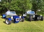
If it helps any, here's a couple of pics of my Chevette rack mounted. Of course, left-to-right, it has to go exactly centered, so there's no question there. Likewise, fore-and-aft, give or take an inch or so for Ackerman adjustment, and as for up-and-down, it has to be pretty close to sitting on top of the lower frame rails. Sooo...the only real question is to the angle of the rack's input shaft. To figure that, I just pulled a string taut from where the middle of the steering wheel would be to the steering rack, and that gave me the angle, so I built the mounts to suit. That worked perfectly.

Of course, I'm using a stock GM column (which ends in a "double D" shape), with a stainless "double D" piece of steering shaft, and a couple of universal joints, to fill in the several feet of gap between the end of the column and the rack. In my case (with a Ford Zetec engine), the steering shaft misses the mounts with lots of room to spare, and my exhaust (only partly fabricated so far) won't be a problem either.

The beauty of doing it this way is that, IF you run into a fouling problem, you can just cut the added steering shaft, ad a pillow block bearing somewhere along the way, and route the steering alongside the frame, closer to the engine, higher, lower, or whatever is necessary. It's acceptable practice to have two universals in line along the shaft without any other supports. If you have 3 or more, there has to be a solid-mounted pillow block or bearing.

Does that make sense? It's hard to explain. But, I have lots of pics if you want 'em...

My pics will give you an idea of the angle of the rack - and, give or take a degree or two (which will be absorbed by whatever universal joints you use), yours will need to be the same.


You do not have the required permissions to view the files attached to this post.

_________________
Scratch building, at continental-drift speed, a custom McSoreley-design framed, dual-Weber 45DCOE carburated, Zetec-engined, ridiculously fast money pit.

http://zetec7.webs.com/


Top
 Profile  
Reply with quote  
PostPosted: July 8, 2011, 9:15 pm 
Offline
User avatar

Joined: March 19, 2011, 10:22 am
Posts: 2395
Location: Holden, Alberta, Canada
Hey Zetec7 I was thinking along the same lines. My rack will be a bit higher becuase my lower A arm pivots are higher up the frame. What u joint did you use on the rack? I was looking at Speedway at theirs, but didn't see the correct spline or might have missed it. Do you have any pics of the steering column placement in the frame? Appreciate the pics posted.

_________________
Perry

'If man built it, man can fix it'
"No one ever told me I couldn't do it."
"If you can't build it safe, don't build it."

Perry's Locost Super Che7enette Build
Perry's TBird Based 5.0L Super 7 L.S.O
Perry's S10 Super 7 The 3rd
Perry's 4th Build The Topolino 500 (Little Mouse) Altered
Perry's 5th Build the Super Slant 6 Super 7
Perry's Final Build the 1929 Mercedes Gazelle


Top
 Profile  
Reply with quote  
Display posts from previous:  Sort by  
Post new topic Reply to topic  [ 365 posts ]  Go to page Previous  1, 2, 3, 4, 5, 6, 7, 8 ... 25  Next

All times are UTC - 5 hours [ DST ]


Who is online

Users browsing this forum: No registered users and 27 guests


You cannot post new topics in this forum
You cannot reply to topics in this forum
You cannot edit your posts in this forum
You cannot delete your posts in this forum
You cannot post attachments in this forum

Jump to:  
POWERED_BY