Miatav8,MstrASE,A&P,F wrote:
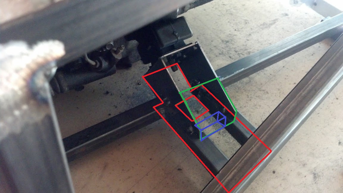
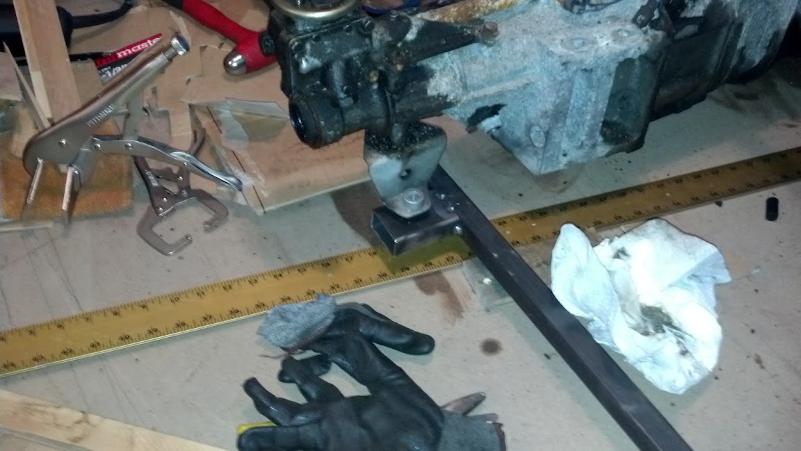
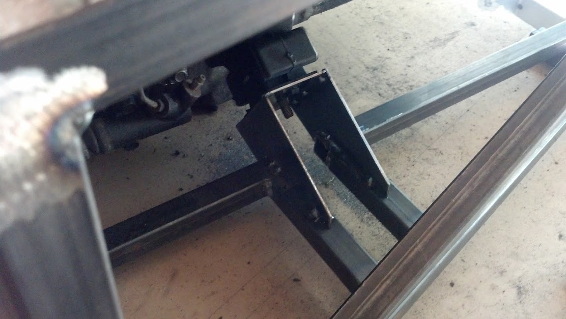
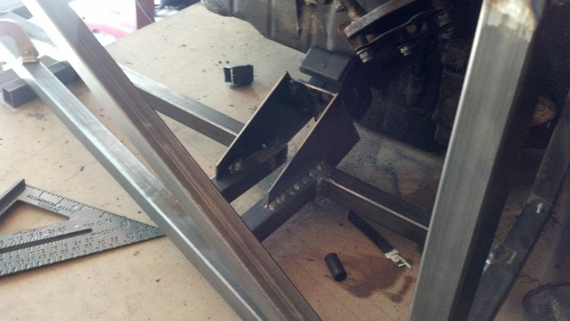
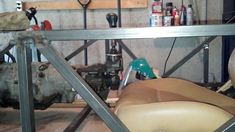
Here is another option for the trans mount for using a T5 mount inverted with the stud facing up. The tube is large enough to fit a deep well socket over the nut, with a washer welded on the end. The framing is .125" steel strip.

I'll be going with this option, as I may have said before... but I have a couple concerns.
1.) The mount, when located at the 'top' of the tube (mounting plate flush with top of tube), puts the mount DIRECTLY in front of the speedometer output. -- To get it any sort of out of the way (and even still, probably way too much in the way), the mount will end up being either at the bottom of the tube, or even lower. While I don't see that being a huge issue... I just don't know. It will put the mount lower than the frame (though, not at low as the oil pan... close), and at that point I gotta start worrying about road hazards. Maybe a skid plate sort of something something in front of it.
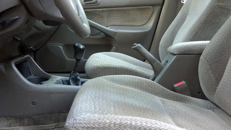
2.) I think I've read that you can somehow make an NB miata electronic speedo gear fit the NA tranny. I'll look into this.. will not only make dealing with the speedo cable a HELL of a lot easier (since it won't be in the picture), but also apparently, this mount. -- At that point, I'd need to swap out the NA cluster for the NB cluster (or at least the speedo), or would force me to use aftermarket gauges... which I've been wanting to do anyway, I guess. Just gotta look up electronic speedo gear options for the NA 5 speed tranny.
I bought 3 of those mounts.. figuring I could maybe use them elsewhere as well (maybe for the rear diff.. not sure. I like the design that you've done above, but also have concerns.. addressed later). They were under 2$ a piece. Hell, maybe later on I can trade them to other locosters for stuff

Or just give them away. I'm a nice guy like that.
Miatav8,MstrASE,A&P,F wrote:
The front diff mount durometer depends on how much arm there is. Longer is better.
If you want a short arm with adjustability, consider a boxed, C channel bracket along the bottom of the diff, extending forward as close as practical to the pinion flange damper. Use a large turnbuckle with 1/2" eyes. The turnbuckle will be in compression under acceleration (see attached for similar approach).

I'm a little.. confused about this post. I see what you drew, I understand that under acceleration, the turnbuckle will be in compression (since the front of the diff will want to rotate upwards). What I'm confused about is:
1.) Where does the top of the turnbuckle attach to? Somewhere along the bulkhead if possible?
2.) You say use a turnbuckle with half inch eyes... most turnbuckles I've found/seen ever, are solid pieces. You also say the length of the turnbuckle determines the durometer. Or do you mean the length of the C channel coming off forward? The durometer is determined by the natural flex in said C channel? I feel like the purpose of using C channel rather than, well, anything, is reduce/eliminate bending. Am I seeing/thinking this wrong?
3.) Does the turnbuckle attachment angle make any difference at all? Best case scenario, should it be angled forward from bottom to top, backward, or true vertical?
Thanks for drawing these up (definitely cleared up a lot of confusion), and thanks in advance for any more guidance you can give on this stuff! -- I'll post some pics of how I'm thinking about mounting the rear differential. It's a bit different than others.. Hopefully it'll be alright.
---------
Side note, I've been ordering suspension parts from Jack.. received all my rod ends and bungs the other day.. starting to get excited!! Hopefully have the drivetrain mounting firm, and have it rolling by the end of the month! We'll see...


 . A whopping $1.71. I may order a couple.