LocostUSA.com

Learning how to build Lotus Seven replicas...together!
It is currently April 17, 2024, 9:39 pm

All times are UTC - 5 hours [ DST ]


Post new topic Reply to topic  [ 369 posts ]  Go to page Previous  1 ... 20, 21, 22, 23, 24, 25  Next
Author Message
PostPosted: May 11, 2015, 8:00 am 
Offline

Joined: February 6, 2012, 1:30 pm
Posts: 200
Location: Southern NH
=O It's been a year. Oof, over a year. -- I've been somewhat active on the facebook page, but have all but died on here.

I have not given up. Even after this poor thing sat in my garage for a year and 5 months... not moving, just getting crap piled all over it... I have not given up.

I finally just said F it, I'm getting back to this thing come hell or high water, I will start working. So I did. And I finished the front suspension in two nights time. I'm just waiting on the aluminum radius rods from Jack that should be getting here around Wednesday. I need to start my rear suspension, which now that I've done the front, I'm feeling pretty confident. I know the ratios I need to hit to get the same geometry as the Miata (or at least, as close as necessary). I have the upper mount points done, I just need to build the arms and set the lower mount points and I should be done. I can't believe I've sat on this for SO LONG because I was anxious about figuring it out absolutely perfectly. Either it will work or it won't. If it doesn't, I will fix it. This isn't going into production tooling... if there is a mistake, I can just rebuild whatever is wrong.

Then steering. I'll be having someone else shorten the shaft, as I don't have a lathe and don't feel comfortable chopping, grinding, and welding hardened steel. I'm hoping they can just cut the end off and rethread, and be done with it. We'll see when the time comes. All that matters is this thing is almost rolling. I never thought I'd see the day!

I need to update my build log site bad... but figured I'd at least get it on here!

Image

_________________
-Brad
Build Log: http://www.BrokeAssSeven.com -- http://locostusa.com/forums/viewtopic.php?f=35&t=13293

This build is already locosting a fortune...


Top
 Profile  
Reply with quote  
PostPosted: May 11, 2015, 9:37 am 
Offline
User avatar

Joined: August 27, 2005, 1:04 am
Posts: 1414
Location: Kamloops, BC, Canada
Good to see you're still building. Never give up, no matter how long it takes. Life happened for me a few times too, but I've got my car on the road now for the first time. I started building it in 2003, but never gave up. I hear you on having stuff just pile up on the car. Between starting my build and now, I moved a couple times, got married, had kids, etc.
Kristian

_________________
V6 in a book frame build. Now registered.
viewtopic.php?f=35&t=7587
viewtopic.php?f=33&t=18172


Top
 Profile  
Reply with quote  
PostPosted: May 11, 2015, 9:54 am 
Offline
User avatar

Joined: October 19, 2012, 9:25 pm
Posts: 3365
Location: Summerville, SC
Don't give up, NH is a long drive for me. :lol:

_________________
Too much week, not enough weekend.

OOPS I did it again
http://www.locostusa.com/forums/viewtopic.php?f=35&t=17496

Blood Sweat and Beers
http://www.locostusa.com/forums/viewtopic.php?f=35&t=15216


Top
 Profile  
Reply with quote  
PostPosted: May 11, 2015, 4:56 pm 
Offline

Joined: February 6, 2012, 1:30 pm
Posts: 200
Location: Southern NH
Thanks guys! :thmbsup: :thmbsup:

_________________
-Brad
Build Log: http://www.BrokeAssSeven.com -- http://locostusa.com/forums/viewtopic.php?f=35&t=13293

This build is already locosting a fortune...


Top
 Profile  
Reply with quote  
PostPosted: May 14, 2015, 11:07 am 
Offline

Joined: August 12, 2012, 6:38 pm
Posts: 1937
Location: worcester county, Massachsetts
Brad right on man! looks good, don't give up!

_________________
The B-3 build log: http://www.locostusa.com/forums/viewtopic.php?f=36&t=13941 unfortunately, all the pictures were lost in the massive server crash

The beginnings of the Jag Special,
https://www.locostusa.com/forums/viewtopic.php?f=36&t=19012
Again, all pictures were lost.


Top
 Profile  
Reply with quote  
PostPosted: June 17, 2016, 8:22 am 
Offline

Joined: February 6, 2012, 1:30 pm
Posts: 200
Location: Southern NH
Hey all! Back at it again! Yet again, over a year since my last update. I mean, at least I'm consistent, right? Even if it's consistently horrible.. it's consistent!

Finally got the 7 moved back over into it's 'working' garage space, after the winter being in the 'storage' garage space (so the wife could park), and being covered in a wonderful pile of junk. Since the last update, not much has changed. I got the aluminum radius rods from Jack, so the front UCA and LCA are 'completed'. Meaning, built, but not fully welded yet. I ought to just do that. Final welding is just so.. final, haha. I've constructed one side's rear UCA and have plans for the LCA done up as well. I would have gotten that finished the other night, but realized I hadn't dimensioned the plan well enough, so rather than go inside and mess around with autocad during the rare few minutes I had to do physical work on the car, I decided to start messing with the steering rack. So, I got that mostly cleaned up, removed all the lines, purged it of fluid, and 'mounted' it in the car. I still need to depower and shorten it, but had to get it in to figure out how much to shorten it by. At 4" off the top of the frame, I'm looking at shortening this thing by about 3.5". If I lower it to 3", that will be slightly more. I think if I'm within .25-.5" of the pivot plane, I'll probably be okay.

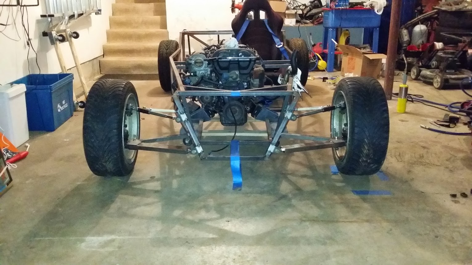
I like Hempy's idea of just winging it. I spend too much time on this thing with mental constipation just worrying and contemplating. I could have been finished with it, if I had just winged the whole damn thing! -- In either case, I'm a genius when it comes to some things, but wishbone and vsusp are not those things. As seemingly easy as they are to use, I just can't figure it out, so screw it! I'm mounting this thing wherever the hell I please! I think 3-4" above the top of the frame will probably do it. The photos below are with it mounted @ 4". With it being full length, the tie rods are at a 14* angle, but that will decrease as the rack is shortened, and the rods are lengthened. If I can get away with it mounted at 3", and clear the LCA's, I'll probably do that to further decrease the angle. This is also using the OEM miata rod ends mounted from the bottom. If I swapped them out with some 323 units, tapered the top of the spindle mount, that would decrease the angle a LOT more. I'm definitely considering this, but need to figure out the proper taper, and if it's worth trying to do on my own. I suspect this is something I can do in the future if I want to, and isn't necessarily necessary at this point.

As far as bump steer, since the inner pivots will be inline with the control arm pivots, I honestly feel like being off by .5" up or down really isn't going to make that huge of a difference. I won't be tracking this car, or taking corners at 100mph, so I'm not super super worried about it. I probably should be more. But again, I overthink -everything-. If anything, it'll create more oversteer, and I'd rather that than understeer anyday. Worst case - I raise or lower the car 1/2" to fix it if it's honestly that bad.

I'm excited again. Every time I work on it, I get so excited. I'm not sure why I keep stopping. (Oh, right, life. Among all of the other things that haven't changed, I now own a custom apparel and vinyl printing business. I have too many jobs/projects/hobbies... I wish I could just choose one).

Attachment:
1.jpg

Attachment:
2.jpg

Attachment:
3.jpg

Attachment:
4.jpg

Attachment:
5.jpg


You do not have the required permissions to view the files attached to this post.

_________________
-Brad
Build Log: http://www.BrokeAssSeven.com -- http://locostusa.com/forums/viewtopic.php?f=35&t=13293

This build is already locosting a fortune...


Last edited by BrokeAssSeven on June 17, 2016, 10:41 am, edited 1 time in total.

Top
 Profile  
Reply with quote  
PostPosted: June 17, 2016, 10:12 am 
Offline
The voice of reason
User avatar

Joined: January 10, 2008, 4:47 pm
Posts: 7652
Location: Massachusetts
Hi BrokeAss, nice to hear from you again!

I can't see the pictures, would you mind uploading at least some of them to our site?

It's OK to wing it but we have had a builder or two that got the rack in a really bad spot. Generally the tie rods land up being a compromise in length and angle between the two control arms...

_________________
Marcus Barrow - Car9 an open design community supported sports car for home builders!
SketchUp collection for LocostUSA: "Dream it, Build it, Drive it!"
Car9 Roadster information - models, drawings, resources etc.


Top
 Profile  
Reply with quote  
PostPosted: June 17, 2016, 10:43 am 
Offline

Joined: February 6, 2012, 1:30 pm
Posts: 200
Location: Southern NH
horizenjob wrote:
Hi BrokeAss, nice to hear from you again!

I can't see the pictures, would you mind uploading at least some of them to our site?

It's OK to wing it but we have had a builder or two that got the rack in a really bad spot. Generally the tie rods land up being a compromise in length and angle between the two control arms...


Woops! Sorry - looks fine on my end, but no big deal, will upload in the future. Thanks for letting me know!

Hm. Hopefully I'm not #3. Like I said, I suppose I can fix it later if I have to. Obviously doing it 'right' the first time is the way to go, but if I keep putting it off, I'll end up never getting it done.

_________________
-Brad
Build Log: http://www.BrokeAssSeven.com -- http://locostusa.com/forums/viewtopic.php?f=35&t=13293

This build is already locosting a fortune...


Top
 Profile  
Reply with quote  
PostPosted: June 17, 2016, 11:26 am 
Offline

Joined: June 15, 2010, 8:29 am
Posts: 651
Location: Duxbury, MA USA
Brad, that is pretty much what happened with my car. I fiddled with it for 3 years or so, then it sat for a year, then I went all out on it for a year and it was done. It was all about maintaining momentum for that last push. I always had a list of things with me that I needed to get...usually some kind of fastener.
This forum was a source of much of the inspiration to "get 'er done"

_________________
Parts left out cost nothing and cause no problems!!


Top
 Profile  
Reply with quote  
PostPosted: June 17, 2016, 11:51 am 
Offline
User avatar

Joined: May 27, 2006, 9:46 pm
Posts: 1954
Location: BC, Canada. eh?
I've been there, too. I lost the use of the shop I was using to build my car in, and it had to sit for 2-3 years while I built my own shop. Plus, of course, work/family/life get in the way sometimes!

I only recently started back into mine again. I don't have the time to go at it hammer & tongs, but I try to "move the peanut forward" a little every week - as long as there's some kind of visible progress, I know I'm still on track.

I'm assuming that the steering rack in your pics hasn't been shortened yet. That should help a lot! I had both the housing and the rack itself shortened (about 3 1/2", IIRC - the rack was shortened by simply cutting off the end opposite the teeth, and cutting new threads on the cut end - easy!), and it made that part of the build a breeze. Trying to work with a rack that's too long can force you into all sorts of undesirable compromises, the sort that compound as the build progresses. In the end, I was able to keep my rack low, with the arms as straight as possible.

Here's an old pic (taken during the 2 or 3 years when I didn't have a shop, and the car was in the family room downstairs :shock: ), showing the suspension at full droop. At normal ride height, the rack arms point a tiny bit down, and go level at just a bit of suspension compression. The idea, of course, was to eliminate bump steer as much as possible. The rack mounts are on slotted plates, so I can adjust for Ackerman a little.

Hope that helps...

Attachment:
P5100175.JPG


You do not have the required permissions to view the files attached to this post.

_________________
Scratch building, at continental-drift speed, a custom McSoreley-design framed, dual-Weber 45DCOE carburated, Zetec-engined, ridiculously fast money pit.

http://zetec7.webs.com/


Top
 Profile  
Reply with quote  
PostPosted: June 17, 2016, 12:02 pm 
Offline
The voice of reason
User avatar

Joined: January 10, 2008, 4:47 pm
Posts: 7652
Location: Massachusetts
What you need is a part they make for cars that use Pinto/Mustang II spindles. It's a tapered shaft that fits into the steering arm and then extends upwards and you can then bolt on a rod end above the spindle. That lets you get the tie rod level or angled up a bit towards the spindle.

Maybe we could get a member with CNC equipment to make up a little batch of those. I'm not using those parts so I'm not completely sure it would work, but it seems like it would...

_________________
Marcus Barrow - Car9 an open design community supported sports car for home builders!
SketchUp collection for LocostUSA: "Dream it, Build it, Drive it!"
Car9 Roadster information - models, drawings, resources etc.


Top
 Profile  
Reply with quote  
PostPosted: June 17, 2016, 12:21 pm 
Offline
User avatar

Joined: May 27, 2006, 9:46 pm
Posts: 1954
Location: BC, Canada. eh?
I agree! If you could raise the outboard ends of the tie rods, the interference with the lower A-arms would be gone - and you could lower the rack a LOT (IMHO, it's way too high presently). Do that, shorten the rack (possibly the tie rods, too - they're generally easy to cut & re-thread), and you're in business.

In my pic, you can see where my rack was cut & TIG welded in the middle of the housing (I had a competent machine shop do this part - they were able to do it on a lathe for absolute precision). BTW, the hubs, brakes etc. on my build are Mustang II...the steering rack is from a Chevy Chevette.

_________________
Scratch building, at continental-drift speed, a custom McSoreley-design framed, dual-Weber 45DCOE carburated, Zetec-engined, ridiculously fast money pit.

http://zetec7.webs.com/


Top
 Profile  
Reply with quote  
PostPosted: June 17, 2016, 1:50 pm 
Offline

Joined: February 6, 2012, 1:30 pm
Posts: 200
Location: Southern NH
zetec7 wrote:
I'm assuming that the steering rack in your pics hasn't been shortened yet. That should help a lot! I had both the housing and the rack itself shortened (about 3 1/2", IIRC - the rack was shortened by simply cutting off the end opposite the teeth, and cutting new threads on the cut end - easy!), and it made that part of the build a breeze. Trying to work with a rack that's too long can force you into all sorts of undesirable compromises, the sort that compound as the build progresses. In the end, I was able to keep my rack low, with the arms as straight as possible.


Correct, not shortened yet! I need to find the proper height to figure out how much to shorten it... Which is a double edged sword, because I'm making that deduction while the rack is still long - so the angles aren't correct anyway. Which is pretty much why I'm winging it! I'm going to lower it from the 4" to the 3" and see if I can figure out if that will work. I think dropping it another inch will probably shorten the rack by .25 to .5 additional.

I'm definitely thinking I'm going to just have the end cut off and rethreaded. Hopefully the shop I'm having cut it down has the correct taps to thread it. They just recently got the lathe from another shop, so I'm not sure what tooling they have.

horizenjob wrote:
What you need is a part they make for cars that use Pinto/Mustang II spindles. It's a tapered shaft that fits into the steering arm and then extends upwards and you can then bolt on a rod end above the spindle. That lets you get the tie rod level or angled up a bit towards the spindle.

Maybe we could get a member with CNC equipment to make up a little batch of those. I'm not using those parts so I'm not completely sure it would work, but it seems like it would...


Interesting. I have access to CNC equipment.. if someone wanted to create this part in solidworks, I could get a quote. Likely a 10 part minimum order though. In either case, we would need to taper ream from the top of the steering arm, since the miata rods mount from the bottom. -- I'm also not sure how awesome a rod end would work in this situation, you think they have enough angular play to work as a tie rod? I guess you could get the extreme angle ones, maybe.

JPS Europa wrote:
Brad, that is pretty much what happened with my car. I fiddled with it for 3 years or so, then it sat for a year, then I went all out on it for a year and it was done. It was all about maintaining momentum for that last push.


It's the maintaining momentum thing that kills me every time! When I only have a few hours a week to work on it, it's hard to even get the momentum started, nevermind maintained!!

_________________
-Brad
Build Log: http://www.BrokeAssSeven.com -- http://locostusa.com/forums/viewtopic.php?f=35&t=13293

This build is already locosting a fortune...


Top
 Profile  
Reply with quote  
PostPosted: June 17, 2016, 3:09 pm 
Offline
User avatar

Joined: May 27, 2006, 9:46 pm
Posts: 1954
Location: BC, Canada. eh?
Assuming it's an outside thread, they don't need taps to cut the threads on the lathe - it's solely in the number of threads per inch (the longitudinal drive takes care of that). Even without metric gearing, a lathe can get close enough over a short length (most metric threads can be cut using standard gearing, and be accurate to around 1 thread per 1,000 0 over, say, 1", there wouldn't be measurable difference from actual metric-geared threads).

I would still consider shortening the housing so you can get the mounts down to within a couple of inches of the frame - I believe it's preferable to have the up & down angle of the tie rods as minimal as possible.

In addition, if you shorten the rack, but not the housing, you'll drastically reduce the total travel of the rack inside it, and you may end up with only a few degrees of steering available! (By way of illustration, if you removed several inches off the rack, but not the housing, the rack could only move inside a tiny bit, from side to side, leaving you with very little steering rack travel).

Ideally, I would shorten the housing precisely the same amount as the rack, to retain its designed internal travel.

_________________
Scratch building, at continental-drift speed, a custom McSoreley-design framed, dual-Weber 45DCOE carburated, Zetec-engined, ridiculously fast money pit.

http://zetec7.webs.com/


Top
 Profile  
Reply with quote  
PostPosted: June 17, 2016, 3:20 pm 
Offline

Joined: February 6, 2012, 1:30 pm
Posts: 200
Location: Southern NH
zetec7 wrote:
Assuming it's an outside thread, they don't need taps to cut the threads on the lathe - it's solely in the number of threads per inch (the longitudinal drive takes care of that). Even without metric gearing, a lathe can get close enough over a short length (most metric threads can be cut using standard gearing, and be accurate to around 1 thread per 1,000 0 over, say, 1", there wouldn't be measurable difference from actual metric-geared threads).

I would still consider shortening the housing so you can get the mounts down to within a couple of inches of the frame - I believe it's preferable to have the up & down angle of the tie rods as minimal as possible.

In addition, if you shorten the rack, but not the housing, you'll drastically reduce the total travel of the rack inside it, and you may end up with only a few degrees of steering available! (By way of illustration, if you removed several inches off the rack, but not the housing, the rack could only move inside a tiny bit, from side to side, leaving you with very little steering rack travel).

Ideally, I would shorten the housing precisely the same amount as the rack, to retain its designed internal travel.


It's an inside thread. Female on the rack, male on the inner tie rod. And yes, of course the housing will be shortened the exact length the rack is shortened. But, I suspect I can do that myself with my mig - I'm somewhat handy with it at this point. I'll probably cut the section out on the horizontal band saw, then cut that section in half, so I can practice on it - not blowing holes through it.

But yes, I also believe the intention is to have the tie rods at a parallel angle to the ground, that is - true horizontal. That way bump steer is exactly the same in bump and droop. Though, I also suspect having them angled slightly down from center would be helpful, as there is more bump than droop over the full suspension travel. Granted, that would allow for toe out until horizontal, then toe in through above the horizontal plane.

The problem is the lower control arms. They get very very much in the way of the tie rods at 0* horizontal. So, they basically have to have some down angle to them so they don't rub (or have to run straight through) the LCA.

_________________
-Brad
Build Log: http://www.BrokeAssSeven.com -- http://locostusa.com/forums/viewtopic.php?f=35&t=13293

This build is already locosting a fortune...


Top
 Profile  
Reply with quote  
Display posts from previous:  Sort by  
Post new topic Reply to topic  [ 369 posts ]  Go to page Previous  1 ... 20, 21, 22, 23, 24, 25  Next

All times are UTC - 5 hours [ DST ]


Who is online

Users browsing this forum: No registered users and 42 guests


You cannot post new topics in this forum
You cannot reply to topics in this forum
You cannot edit your posts in this forum
You cannot delete your posts in this forum
You cannot post attachments in this forum

Jump to:  
POWERED_BY