LocostUSA.com

Learning how to build Lotus Seven replicas...together!
It is currently April 19, 2024, 6:34 pm

All times are UTC - 5 hours [ DST ]


Post new topic Reply to topic  [ 253 posts ]  Go to page Previous  1 ... 11, 12, 13, 14, 15, 16, 17  Next
Author Message
PostPosted: November 29, 2016, 3:05 pm 
Offline

Joined: May 1, 2012, 9:43 am
Posts: 336
Location: Sidney, BC, Canada
I have a plan in place for the tachometer, though I don't know if it will work: I took the instrument cluster from the Escort apart and found that each instrument is actually on a separate board inside. So I took the tach out, and plan to mount in inside of a piece of ABS pipe which will act as the housing and bezel (suitably painted). The faceplate on the tach isn't round though, it's kind of an odd shape, so I'll probably have to make a new one. Might as well make it black writing on a white background to match the other gauges I have.

Anyway, while I'm trying to figure out instrumentation issues, I changed gears slightly to work on the lights. I figured it's best to get as much of the wiring as possible out of the way before adding a scuttle as it might be difficult to get to later. I cut down the fuse box from the Escort so that it contained just the fuses and not all of the other interconnections, and started adapting some relays for the marker and headlights, etc. I now have a mostly functioning light stalk on the steering column.

The next obvious step was to mount the tail lights, since I wanted my functioning light stalk to actually have something to light up besides the headlamps. I kind like the look of the early Doonkervoort D8 tail lights and wanted to try to replicate that. What I got is... well, it's a start. I used some 4" ABS pipe as a mount for my LED trailer lights, having to bore it out a bit with a die grinder since the body of the lights is actually slightly larger than 4" (I think around 4.2"). To hold the light in the pipe, I added a bezel made of a short pipe section which fits over the front of the light, and will be glued to the rest of the pipe when I'm satisfied with the fit. I think these things will requrie a fair bit of finishing with body filler to make them fit nicely...


You do not have the required permissions to view the files attached to this post.


Top
 Profile  
Reply with quote  
PostPosted: November 29, 2016, 3:25 pm 
Offline
User avatar

Joined: May 27, 2006, 9:46 pm
Posts: 1954
Location: BC, Canada. eh?
Well now, those are pretty cool! And, a true example of "thinking outside the box"!! I've been known to browse around PA for hours, looking at various cheap items (particularly in the surplus section), trying to figure out how to use them in my build.

I'm also a firm believer in "reduce, reuse, recycle", and an inveterate scrounger, to boot. Bits of metal (or plastic, or...) sticking out of garbage bins have been known to make their way into my shop, and into my build, not to mention ABS pieces I've collected from my garage build, shop wiring, etc. If you keep your eyes open, and your imagination engaged, it's amazing what you can find!

BTW, that ABS, when turned on a lathe, can be worked & polished amazingly well...

As an aside - I've been thinking about getting one of those PA shrinker/stretchers...after using yours, do you recommend them?

_________________
Scratch building, at continental-drift speed, a custom McSoreley-design framed, dual-Weber 45DCOE carburated, Zetec-engined, ridiculously fast money pit.

http://zetec7.webs.com/


Top
 Profile  
Reply with quote  
PostPosted: December 14, 2016, 11:31 am 
Offline

Joined: May 1, 2012, 9:43 am
Posts: 336
Location: Sidney, BC, Canada
Zetec, I'm not sure if I have enough experience working with sheet metal to recommend this particular shrinker/stretcher. I mean, it works, but I have no basis for comparison to say whether it's a "good" unit or not. I think if you're going to be doing a lot of sheet metal work then having a separate shrinker and stretcher might be a good idea, as it takes a few minutes to switch the jaws on this one. Also, you definitely need to have it bolted down to a stand of some sort. In order to use this one I have to clamp it to a couple long pieces of angle iron, otherwise it tries to fall over backward when you push down on the handle.

I've been thinking about how to wire up my marker lights and turn signals. The rears are easy, since the marker, signal, and brake lights are all separate. However, for the front and side markers I bought some 2" LED round lights from PA (4 x amber and 2 x red). These are the equivalent of single filament (only two wires), so I have to get creative on how to get them to:
a) flash as turn signals with the marker lights off
b) turn on as marker lights
c) flash off as turn signals when they are on as marker lights.

The schematic below is what I came up with. Anyone have any comments? Right away one thing that bothers me is that the rear signal lights will flash out of phase with the front/side ones when the marker lights are off (i.e. when 12v comes from the flasher for that side, the rear turn signals will light up, whereas the front/side markers will go off).

BTW, despite being LED lights, these little marker lights seem to be not sensitive to polarity. I've tried hooking the wires up in both orientations to a battery and they come on either way, which I found interesting. I'm not sure how they're wired internally to achieve this.


You do not have the required permissions to view the files attached to this post.


Top
 Profile  
Reply with quote  
PostPosted: December 24, 2016, 2:42 pm 
Offline
User avatar

Joined: August 27, 2005, 1:04 am
Posts: 1414
Location: Kamloops, BC, Canada
I used led truck lights for my tail lights, and they are only single filament equivalent too. I used resistors and diodes to turn them into tail/brake lights. I used trial and error to come up with the resistance that would give me the right amount of light output for my tail lights. They still work good after a few years, and no extra relays to worry about. For the front signals I didn't bother with keeping them on as side markers when not flashing, but I'm sure the same solution would work just as well up there. I'd just have to run the tail light wires through another resistor and diode for each front signal.
Kristian

_________________
V6 in a book frame build. Now registered.
viewtopic.php?f=35&t=7587
viewtopic.php?f=33&t=18172


Top
 Profile  
Reply with quote  
PostPosted: December 24, 2016, 3:42 pm 
Offline

Joined: February 8, 2014, 10:47 pm
Posts: 781
Location: Cornelius OR
I was confused as the bulbs in the drawing are incandescent, not LED.

Image

If the LEDs don't block reverse current some of the lights may not behave as expected.

Electronic 2 pin flashers to try
EL-12
BP-232
EF-32


:^) Merry Christmas!

_________________
Honey anyone?


Last edited by Bent Wrench on December 24, 2016, 5:03 pm, edited 2 times in total.

Top
 Profile  
Reply with quote  
PostPosted: December 24, 2016, 3:46 pm 
Offline
User avatar

Joined: May 27, 2006, 9:46 pm
Posts: 1954
Location: BC, Canada. eh?
As far as the front & rears flashing out of phase, that shouldn't matter - I've had GM vehicles where the factory design has them doing exactly that.

Personally, I like turbo_bird's idea of just using resistors, rather than relays, to accomplish this task. Nothing wrong with relays, of course, but if he could advise as to the necessary resistors, it might make a simpler (and cheaper) setup. I only want to use relays for high-power electrical bits - some of my low-powered stuff (windshield washer pump, for example) will be wired direct for simplicity's sake, and that includes the LED lights I'm using.

For those who haven't considered it, there are special turn signal flasher units designed for LED bulbs. I don't think it's a problem when using a combination of regular bulbs & LED's, as the regular bulbs would produce enough resistance to operate the flasher unit, but if you're going with all-LED's for signals, you either need to use one of the special flashers, or add in enough resistors to mimic the resistance of at least one incandescent bulb to activate a standard flasher unit...

_________________
Scratch building, at continental-drift speed, a custom McSoreley-design framed, dual-Weber 45DCOE carburated, Zetec-engined, ridiculously fast money pit.

http://zetec7.webs.com/


Top
 Profile  
Reply with quote  
PostPosted: December 24, 2016, 4:38 pm 
Offline
User avatar

Joined: August 27, 2005, 1:04 am
Posts: 1414
Location: Kamloops, BC, Canada
zetec7 wrote:
As far as the front & rears flashing out of phase, that shouldn't matter - I've had GM vehicles where the factory design has them doing exactly that.

Personally, I like turbo_bird's idea of just using resistors, rather than relays, to accomplish this task. Nothing wrong with relays, of course, but if he could advise as to the necessary resistors, it might make a simpler (and cheaper) setup. I only want to use relays for high-power electrical bits - some of my low-powered stuff (windshield washer pump, for example) will be wired direct for simplicity's sake, and that includes the LED lights I'm using.

For those who haven't considered it, there are special turn signal flasher units designed for LED bulbs. I don't think it's a problem when using a combination of regular bulbs & LED's, as the regular bulbs would produce enough resistance to operate the flasher unit, but if you're going with all-LED's for signals, you either need to use one of the special flashers, or add in enough resistors to mimic the resistance of at least one incandescent bulb to activate a standard flasher unit...

I think I ended up around 150-180 ohms, but I don't remember for sure. It would of course depend on the current draw needed for however bright you want your taillights or side marker lights. As far as LEDs and regular signal flashers go, you can use a regular bulb or a large power resistor in parallel with a signal light bulb to add enough current draw to make them flash at the proper rate. My car has the signals on the sides of the nose cone with an RC car battery connector going to the main harness. If my signal lights flash really fast, that means I forgot to hook the fronts back up.
Kristian

_________________
V6 in a book frame build. Now registered.
viewtopic.php?f=35&t=7587
viewtopic.php?f=33&t=18172


Top
 Profile  
Reply with quote  
PostPosted: December 27, 2016, 1:52 pm 
Offline

Joined: May 1, 2012, 9:43 am
Posts: 336
Location: Sidney, BC, Canada
I thought about going with resistors for the front marker lights, but what you end up with then is a bright turn signal and a slightly dimmer marker light, right? I'm not sure if I want to make the front markers dimmer, they are not super bright to begin with. Plus when you have lights on with a turn signal you would get bright-dim-bright-dim rather than on-off-on-off, correct? Do you not require front marker lights to be on in BC turbo_bird? I think it's part of the Alberta highway code.

The tail/brake lights are not a problem as they are "dual filament" LED trailer lights so they have a separate input for bright brake lights and slightly dimmer tail lights. The rear turn signals are actually the same light in amber instead of red, so if I wanted to I could have those on dim too, but I think that would look goofy so I'm just using the bright input for the turn signals. The only ones that are single input are the front and side markers.

Bent Wrench, sorry for the confusion. I used incandescent bulbs in the diagram simply because it was a quick drawing modification in paint, but the concept is the same. I looked inside one of the marker lights I have and they contain a bridge rectifier before the LEDs which makes them insensitive of polarity. I think this was done precisely so that they are completely compatible with incandescent bulbs in applications which may see reversed current flow like this one.

I was planning to modify my flasher relay to slow it down with a lower load of LED bulbs, but I noticed that for less than $3 I can buy a flasher already made for lower LED loads on ebay. For that price I'm not going to bother trying to modify mine.

Anyway, with the front marker lights installed, I decided to start working on the side body panels. After that I may try finishing up the scuttle. Hopefully I'll get a bit done this week as I took a couple of vacation days to net me the whole week off work, and the weather is supposed to be just below freezing the next few days (yay Chinook!) which makes it quite tolerable in the garage. A friend of mine gave me an old wood stove that he made which I'm going to try to install before next weekend so hopefully I'll be able to keep working as the temps drop back down to around -20 C again.


Top
 Profile  
Reply with quote  
PostPosted: December 27, 2016, 2:12 pm 
Offline
User avatar

Joined: August 27, 2005, 1:04 am
Posts: 1414
Location: Kamloops, BC, Canada
Correct, you'd end up flashing bright/dim instead of on/off if you use resistors. My front signals are only on as signal lights, not side markers. I don't remember if side markers are required to be on all the time or not, different inspectors want different things. As an example, the guy that looked at my car wanted the lights on whenever the ignition was running, like what is required for motorcycles. All I did was wire the headlight power circuit to the keyed power instead of the headlight switch. Maybe with headlights on all the time it's a non issue?
Kristian

_________________
V6 in a book frame build. Now registered.
viewtopic.php?f=35&t=7587
viewtopic.php?f=33&t=18172


Top
 Profile  
Reply with quote  
PostPosted: January 12, 2017, 11:32 am 
Offline

Joined: May 1, 2012, 9:43 am
Posts: 336
Location: Sidney, BC, Canada
Happy to report that the wood stove is working well and I'm able to get the garage up to about 8 C when the outside temperature is around -20 C. This has allowed me to finish up the lights, and get the side panels and scuttle largely done. There are still a few details that I'm not happy about, but I'll leave those for later.

My scuttle is about twice as long as most people's since my firewall is vertical from floor to hood right at the front of the footwell instead of having a "shelf" like most locosts. I connected the firewall to the dash hoop using four 1" steel staps to make the whole thing more rigid and then skinned it with .040" Aluminium. It was pretty fiddly to get it more or less the way I wanted it, and the dimensions didn't come out perfect, but it looks alright. The edge facing the driver is rolled, and the sides are tucked under and attached to the longitudinal tubes on the inside. All of my body panels are attached using sheet metal screws instead of rivets so I can remove them quite easily.


You do not have the required permissions to view the files attached to this post.


Top
 Profile  
Reply with quote  
PostPosted: January 31, 2017, 12:40 pm 
Offline

Joined: May 1, 2012, 9:43 am
Posts: 336
Location: Sidney, BC, Canada
After going back and forth on the build-or-buy question for the nose, I finally decided to try my hand at building one. While I like the Kinetic nose, with the exchange rate between USD and CAD as well as shippng from the states, I thought it would be worth it to at least give it a go.

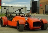
First I made a wireframe buck from some 3/16" steel rod bent up by hand. I tried my best to get it symmetrical though I'm sure it's far from perfect.
Attachment:
IMG_20170128_151818sm.jpg


Next I skinned the frame using poster paper. Each of the panels was cut such that only a single curve was required for each section, which meant that in theory I could reproduce that in metal. However, that would require welding the individual panels together, and I don't have any good means for welding thin aluminum. Plus there would be some sharp transitions that I don't like.
Attachment:
IMG_20170129_143017sm.jpg


The logical thing then is to use this as a buck for a fiberglass part. The next step is to add some thickness to it so that I can sand it down to the final shape and smooth it out. I decided to try doing this with paper mache as the base to give some rigidity, and then some sort of plaster of foam as the filler. I did the first paper mache layer last night, although I forgot to snap a picture. In hindsight I should have coated it with clingwrap or something before addind the wet newspaper, as the moisture caused the panels to sag. Interestingly, the poster paper panels that had the picture side out (instead of the white side out) absorbed a lot less water and were mostly unaffected. I didn't know that the ink they used is so waterproof.


You do not have the required permissions to view the files attached to this post.


Top
 Profile  
Reply with quote  
PostPosted: February 1, 2017, 1:01 pm 
Offline
User avatar

Joined: October 24, 2008, 2:13 pm
Posts: 5326
Location: Carlsbad, California, USA
Congratulations, that's a very innovative approach. It's looks darn good in the photos.

When you watch the various panel beater videos like from Covell, Lazzie, etc., on YouTube it all seems so simple. But, after trying it a couple of times at metal meets and a class, I can tell you there are many subtle issues to handle, and your fiberglass approach is probably more realistic in your situation without anyone skilled to help you.

I still plan to do some panel beating myself, but I know what I'm getting into, and I'm also fortunate to have some skilled guys in my area willing to share their expertise. Round one of my build is fiberglass pieces that I got from Jack!

Cheers,

_________________
Damn! That front slip angle is way too large and the Ackerman is just a muddle.

Build Log: viewtopic.php?f=35&t=5886


Top
 Profile  
Reply with quote  
PostPosted: April 19, 2017, 6:12 pm 
Offline

Joined: May 1, 2012, 9:43 am
Posts: 336
Location: Sidney, BC, Canada
After working on the nose for some time, I'm undecided whether it was worthwhile to tackle it myself rather than buying it. I definitely need more practice doing fiberglass work if I'm going to get good at it, but the finishing work required on something like this is time consuming with little payoff. Anyway, the nose is far from complete yet, but I've decided to take a break from it and do some other parts until my gumption reservoir is refilled.

I cut out a windshield template out of 1/2" plywood for bending the frame in the book fasion, and made a cardboard template to take to the glass shop to have a piece of AS1 laminated safety glass cut to size. They estimated $87 CAD, which is much lower than I expected. My windshield will be more tapered than most as I was trying to match the profile of the rear roll bar for aesthetics. We'll see if that ends up being a good choice or not. I'm having a bit of trouble sourcing the aluminum channel for the frame locally - shops here have channel that is 3/4" or larger, and the only shop that has channel to fit 1/2" plywood only sells it in 4 foot lengths. Some more looking is required.


You do not have the required permissions to view the files attached to this post.


Top
 Profile  
Reply with quote  
PostPosted: April 19, 2017, 6:40 pm 
Offline
User avatar

Joined: May 27, 2006, 9:46 pm
Posts: 1954
Location: BC, Canada. eh?
If it's of any help, I used 3/4" X 3/4" aluminum, and so far it's looking good. Because the aluminum is 1/8" wall thickness, the inside measurement is exactly 1/2". I'm planning on using 1/4" laminated safety glass (a common size, and acceptable to Motor Vehicle inspectors...especially if it has the engraved DOT "bug" (certification) in the corner). That leaves 1/8" between the sides of the glass, and 1/4" between the outer edge of the glass & the bottom of the channel - in my view, that's perfect for protecting the glass.

I ordered a 10' section of the aluminum from Metal Supermarket in my area. They had the channel for me in a couple of days. They suggested not bothering to anneal the channel before bending, but I wasn't sure about that, so I annealed the heck out of it. I'm glad I did - the radii at the top corners of the windshield are pretty tight, and even with the custom-made, heavy steel channel bender we had for doing this, it was still a struggle without damaging the alloy in the process.

_________________
Scratch building, at continental-drift speed, a custom McSoreley-design framed, dual-Weber 45DCOE carburated, Zetec-engined, ridiculously fast money pit.

http://zetec7.webs.com/


Top
 Profile  
Reply with quote  
PostPosted: April 19, 2017, 7:11 pm 
Offline

Joined: May 1, 2012, 9:43 am
Posts: 336
Location: Sidney, BC, Canada
Hey Zetec, that 3/4" outside dimension with 1/8" wall thickness channel is what I've been looking for, but no luck so far. My plan was to do exactly as you said, ~1/4" glass with about 1/8" of gasket on each side for a total thickness of 1/2" inside the frame. The channel sections that I've found in 8' lengths are 3/4" inside dimension and larger, with either a 1/16" or 1/8" wall thickness. I've considered ordering it and having it shipped but it seems like one of those things where shipping would come out more than the product cost. Maybe I'll have a look in Calgary next time I'm there, there's probably more options available.


Top
 Profile  
Reply with quote  
Display posts from previous:  Sort by  
Post new topic Reply to topic  [ 253 posts ]  Go to page Previous  1 ... 11, 12, 13, 14, 15, 16, 17  Next

All times are UTC - 5 hours [ DST ]


Who is online

Users browsing this forum: No registered users and 17 guests


You cannot post new topics in this forum
You cannot reply to topics in this forum
You cannot edit your posts in this forum
You cannot delete your posts in this forum
You cannot post attachments in this forum

Jump to:  
POWERED_BY