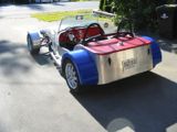
Bent up some Ram Board to simulate how the side panel a lengthened nose cone might look:
Attachment:
P4104495-1.jpg
Kind of like the look.
Then ADD struck and I moved on to work out some dashboard details. The plan is to make the dash panel out of 6mm marine plywood, Bruynzeel mahogany or the like. But for the cardboard aided design phase, Formica was used.
The dash bulkhead is fairly close to the steering wheel and the dash panel itself is relatively narrow (6”.) This plus the bulkhead’s truss–like internal structure and the required dash mounting t@bs limit the space available for instruments and switches. So figuring out the workable locations while retaining descent ergonomics became a bit of a challenge. So ADD struck again and it was off for more research on instrument options and switch gear.
The plan is to keep instruments to the basics (tach, speedo, oil pressure, coolant temp, volts and fuel level) and minimize the number of switches (Engine off/on/start, turn signals, horn, headlight controls (3), wipers, hazard and battery disconnect.) Mounting switches on the removable steering wheel was ruled out to avoid requiring a quick disconnect wiring harness.
Here’s my current thinking on layout:
Attachment:
P4104496-1.jpg
The pencil lines on the dash panel show the truss tube and t@b locations that need to be avoided. That led to placing a quad gauge in the middle. The tach and speedo will be visible through the steering wheel. All three gauge housings are 3 3/8” units, probably from Speedhut. Left and right turn signal activation is with momentary buttons, the red dots on the dash at 10 and 2. The horn button will be at the purple dot near the quad gauge at 7 o’clock.
The shift lever sits pretty close to the lower dash panel. That means rocker switches rather than toggles for the less frequently used switches. Per the Carling switch catalog, the necessary switches with the proper engraved icons (e.g., “Hazard”) can be configured eliminating the need for additional labels.
Attachment:
P4104497-1.jpg
A keyless ignition lock is planned, so a single toggle will provide for off/run/start. Here it is under the red cover guard, mounted to the side insert panel of the dash bulkhead.
Attachment:
P4104498-1.jpg
The toggle’s location is far enough out of the way so accidentally “killing” the ignition shouldn’t happen, but still close enough for emergency shut off if needed. A steel panel with dimpled lightening holes will replace the poster board mockup insert one of these days.
The battery disconnect switch may float to the right or left on the dash a bit based on wire routing and clearance for components mounted under the scuttle. And a 12v accessory plug will find a home somewhere.
After working out the above layout, some of the dash mounting t@bs had to be moved to clear the revised instruments/switch locations. Fortunately they were only tacked in or not yet added. Still to be incorporated in the dash bulkhead is a mounting t@b for the front-end of the removable cockpit diagonal brace. Biggest concern here is assuring clearance for the shift lever in all five gears when the brace is in place. Oh, and any impacts on the instrument/switch layout.
Also starting to look at windshield mounting. Given the one-off aluminum scuttle, I’ll likely need to make up my own supports. Whoops, there goes that ADD again.