Well, it's been months since I made my last confession...uh, contribution...to my build log. So, here's a bit of an update.
Nothing major, really, just a bunch of little detail items that needed doing. Still, they're all stuff I wanted to get done before I get to disassembly & frame paint, as it seems there's always one more tab that needs to be welded on. Until these detail items are done, I can't really know that I've finished all the welding I need to do on the frame before I can paint it.
Let's see...I made up a mount for my ignition module on the rear of the cylinder head, in the original Ford location. Of course, since I'm using a Quad4Rods ignition module, which is based on an '80's GM OBD-1 unit (Ehrlich-built, and modified to operate permanently in "run-home" mode with appropriate 2D mapping), it's different from the Ford module mount. I made up an adapter plate out of 14-gauge aluminum that marries the two together rather nicely. It also adds a substantial air gap between the two, so the module should stay nice & cool.
Attachment:
ignition module mount small.jpg
While I was at it, I had to make up a plug wire set to join the GM module to the Ford Zetec plug wires. This turned out to be fairly simple - chop off the Ford coil ends of the wires & install GM coil ends. Of course, it was a lot more fiddly than it sounds...
Attachment:
ignition module and plug wire set small.jpg
I decided it was time to fabricate the horizontal and vertical panels for the scuttle/firewall. I'd bought a half sheet of 14-gauge aluminum, and decided to use that - the wiper motor, etc. will be mounted on it, so it needed to have some rigidity. I made up patterns for the panels & cut them out with a jigsaw. Unfortunately, what I hadn't noticed was that the steel foot om my jigsaw had a burr on it, so it left a shallow, wobbly groove all around the periphery of both panels. I didn't think it was a problem initially, until I realized just how deep the grooves were. I couldn't use the other sides of the panels, as they had some white patches of corrosion, which don't harm the metal but can't be buffed out. So, I started sanding. And sanding. And more sanding. I worked my way down from 220 grit to 1500 wet, and finally got the gouges out. Of course, the panels ended up more or less mirrored. Wow! Bling!! Unfortunately, you can scratch the surface by laying a clean cotton towel on it. *Sigh* - I expect I'll be doing a LOT of polishing over the years! It does look nice, though...
In this pic, the panels are merely mocked up - later, I added countersunk stainless screws on the horizontal panel as, for some reason I can't fathom now, I decided I really wanted a smooth, flush surface on the horizontal panel. As the EZ-Wiring fuse panel was to be mounted in fabricated steel box underneath this horizontal scuttle panel, it needed to have a flush-mounted, hinged door to allow access to the fuse panel. The fuse panel access door is just visible in this pic, dead center in the horizontal alloy panel (just behind the oil filler cap, in this pic).
Attachment:
firewall panels mockup.jpg
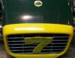
The (hinged) fuse panel door needed to have some method of allowing me to open it. Again, sticking with the "flush" theme, I decided on a finger-push, spring loaded, small tab-you-can-stick-your-finger-in-to-open-the-door arrangement.
Attachment:
fuse panel door lift 7 small.jpg
Attachment:
fuse panel door lift 6 small.jpg
The little tab was tricky to fabricate, not having a mill (*Sigh!*). I ended up using a piece of 3/16" aluminum, cut larger than the hole, and using a hacksaw to cut into the edge all the way around, until the edge had 2 lips. Then, I used the hacksaw to remove one of the lips (so that the remaining thickness of the piece that was the same size as the hole was also the thickness of the main panel), and hand-filed & sanded it all to final shape. It turned out rather well, I thought - not perfect, but then this stuff is all hand made and, since I'm FAR from perfect, I think it's passable.
The hinge/spring is made from garbage - a piece of cast-off banding from a bundle of lumber. It really is great stuff - easy to work, has a nice spring temper, and...it's FREE!!. A few countersunk 1/8" rivets, and it's done.
Since my last post, I've also fabricated the windshield frame. That was fun (NOT!). It's amazing how much force it takes to bend that 3/4" X 3/4" aluminum square channel. It's also amazing how difficult it is to get the absolutely precise bends required to match the scuttle profile, and how much the aluminum gets gouged up in the process. It took many, many hours to get the aluminum looking decent again.
I also pondered how to assemble the frame once I have the glass for it (I'll be using 1/4" laminated, DOT-approved safety glass). Obviously, the frame has to come apart somehow, and as the bottom is the widest section, it makes sense to slide the glass into the frame from the bottom. That, of course, requires a means of joining the bottom section of the frame back to the main section, securing it in place, and capturing the glass in some kind of rubber cushion, all at the same time. Here are a couple of pics of the frame itself (pre-polishing) and the method I came up with to join the frame together. The tabs you see have since been drilled & tapped for a couple of countersunk 10-24 NC screws on each side - the screws go through the bottom ends of the frame legs, and into the tapped holes in the tabs. Seems to work well, and appears nice & solid. The screws are completely hidden by the stanchions when the frame is mounted.
Attachment:
windshield frame small.jpg
Attachment:
windshield frame joint 5 small.jpg
I also made mounts for my glorious, England-sourced front cycle fenders. It was a complex job, and I have to admit having shamelessly copied the ingenious efforts of others on the forum. They're nice and strong, yet just a tiny bit flexible, so hopefully they won't shake themselves apart. The steel forks that go up under the fenders have upturned vertical edges, and the fenders themselves will have 20-gauge steel panels (with downturned vertical edges, so the verticals can be bolted together). The steel panels will be bonded to the underside of the fiberglass fenders with 3M 5200, due to its incredible strength of adhesion, and being completely impervious to oil, water, etc.. The adhesive strength of this stuff will be close to 2 tons per fender. That oughta do it. It's what Cat***ham uses to attach their fenders, after all!
Attachment:
front fender mount small.jpg
As those who have been following my thread about cutting a Lucas wiper cable know, I've also been working on my wiper system. While the concept is deceptively simple, the actual application is rather complex. There's a LOT of precision required to get all those bits & pieces singing in harmony from the same song sheet.
Cutting the inner cable turned out to be a doddle. I was worried initially (hence, the thread I started) that the outer, spiral around the outside of the cable would go "SPROING!!" once I cut it. Several people responded that they had no trouble with this, and I was elated! Then, another wrote in...his cable went "SPROING!!" when cut. So, I decided on a plan - I wrapped (tight!) the area nearest the cut with masking tape, and cut it with a zip disc on my angry grinder. So far, so good. To be absolutely certain it would stay together, I used my MIG welder to do a teensy, tiny weld, joining the outer spiral to the central core. It was nerve-wracking, but it worked. I built the end up a bit with more weld, shaped the end into a bit of a cone (so it would feed through the wheelboxes), and polished it up. It seems to work great, and I doubt it will ever...uh..."SPROING!!" in the future.
Attachment:
wiper cable end crop 1.jpg
On to the wiper system itself...I've mounted the Lucas drive motor onto the horizontal scuttle panel, which seems to be the right place for it. I bought some 5/16" brake line & curved it so that it goes from the motor to the passenger's side wheelbox in a smooth arc. Caution: the Lucas cable should NOT have to take more than a 3" radius bend, or it will drag badly. In this case, the radius was about 8" or more, so it should be good.
Attachment:
Wiper system 2 small.jpg
In this pic, the wheelboxes etc. are mocked up...and working!! It's surprisingly quiet, too, given that I haven't re-greased the wheelboxes or cable since I cleaned them up. The sharper-eyed among you will notice that the angled ferrules (through which the wiper shafts protrude) are not the original, British, chrome-plated pot-metal items.
As it turns out, wiper shafts need to protrude from the scuttle at precisely 90* to the windshield surface, or as close as is possible. As our Locost windshields are generally rather vertical, compared to British offerings (such as the MGB, from whence my wiper system came), these ferrules are utterly wrong for our application. The complementary angle to the windshield turned out to be around 55*-60*, rather than 90. When the wiper arms are in the vertical position, all is fine...but as they sweep down toward the park position, they lean over to the point where the blades are almost on their sides. That would NOT work. The only option was to fabricate new ferrules, on a much finer angle. I used some 1" aluminum stock, boring it lengthwise to 5/8" to fit over the wheelbox spindles, and slant-cutting them as fine as I could. You can easily go too far on this...the problem is that the gearbox etc. on the back of each wheelbox will hit the underside of the scuttle skin, if you try to go too far. In the end, I got the angle up to 82*...as close as possible, given the angle of my windshield.
Anyway, here's the system, mocked up & functional:
Attachment:
wiper system 3 small.jpg
Attachment:
wiper system 5 small.jpg
...on to a follow up post - I've reached the limit on pics in this one, apparently