Joined: February 20, 2006, 11:18 am Posts: 3186 Location: Lexington, KY
Beautiful baby, nice car! I'll have to come see both!
I thought I noticed a slightly larger garage in your FB pix...
-dave
_________________ ...nowadays people are so intellectually lazy and lethargic that they can't build ANYTHING with their hands. They'll spend hours watching whiny people marooned on an island, but won't spend a second adding anything to the world. -weconway Visit my [Locost 7 build log]
Joined: July 17, 2008, 9:11 am Posts: 6416 Location: West Chicago,IL
Cute baby.
You've been busy even though you haven't been working much on the car. Your build was one I was following closely when I started cutting steel. Glad to see you didn't give up. And welcome back. I hope to see more of your build in the coming months.
Chuck
_________________ Chuck.
“Any suspension will work if you don’t let it.” - Colin Chapman
Joined: March 25, 2007, 12:36 pm Posts: 562 Location: Phoenix, AZ
Congrats!
I still get emails when you update your picasa album and thought I spotted a few changes!
_________________ Georgia Tech Ride and Handling Engineer for a major car company Locost finished - book frame, IRS, '84 celica GTS donor, '99 tacoma 2rz motor with a turbo, megasquirt DIYPNP. Getting rebuilt with new IRS, F20C "the all-consuming time-sucking car, which I really enjoy working on" -KB
Joined: December 21, 2006, 2:30 pm Posts: 337 Location: Louisville, KY
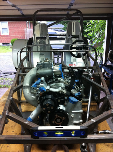
A little bit more progress to report.
Finally got around to running the 220V power out to the garage for my welder, so I've been able to make some more headway on my car lately.
Front Suspension: From very early on in the project I decided I wanted very quick ratio steering. With very little room in the driver's compartment to "saw" away at the wheel, I wanted racecar-like precision and agility. Realizing that the $700 for a custom steering rack could be used elsewhere in the project (AIM dash/data logger???) I decided that a modified street car rack would be the best route. After looking around for a while and thinking of all the street cars I've driven with good steering, the Honda S2000 stood out. I knew going in that it was a complex electric power steering type rack, and research yielded almost no info on de-powering them. But regardless, one came up cheap so there was little risk in giving it a try. And boy am I happy I did! This thing is gonna be so sharp. The S2000 already has some of the sharpest steering out there, and add to that the steering arms on my 2nd gen RX7 spindles are ~1" shorter than those on the S2000 spindles further quickening the ratio, it should work out really well. All that and after materials and a couple bushings I'll have right about $100 when it's all said and done!
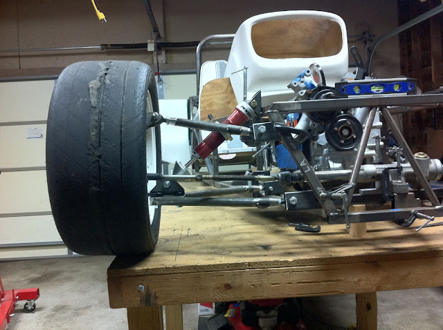
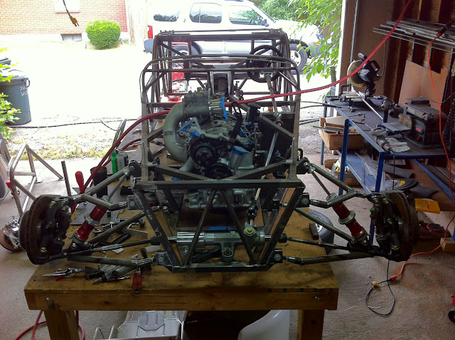
Also finally settled on front suspension geometry and fabbed pickup points, vertical braces, and finish-welded it all to the frame. Decided on doing without an anti-roll bar, so picked the highest roll center that still gave me good camber gain while geometrically resisting roll as much as possible. Only tricky part was having to lower the steering rack down more than I expected to combat a bumpsteer out condition I was experiencing. Finally put two front wheels on the car for the first time last night! Dangerously close to having a roller people!
On to a barrage of pics!
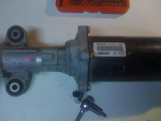
Steering rack as I received it
Complete with massive (and HEAVY, could double as a boat anchor) electric motor for EPS
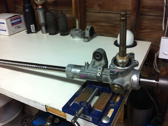
And now all slimmed and trimmed. The steering rack boot will cover the grooves in the rack for the EPS. This is after the housing was cut but before I settled on a rack width, I ended up cutting quite a bit out of it. Still need to get the material to complete the driver's side of the housing where I will attach the boot and also press in a bushing
Plotting pickup point locations and checking for camber gain/bump steer in reality
More mockup
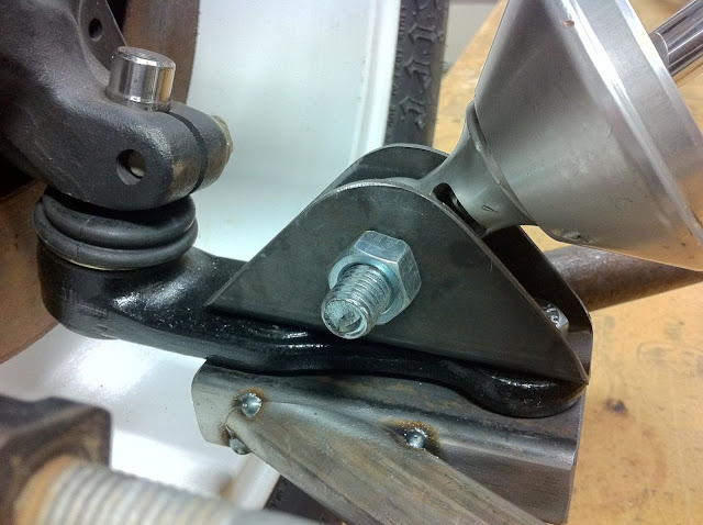
Lower shock attachment point
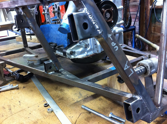
Finally the decision was made! Pickup points finish welded to the frame.
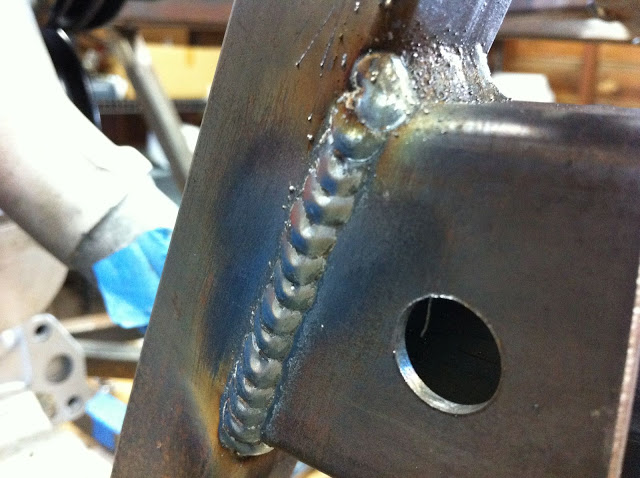
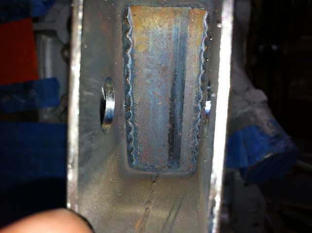
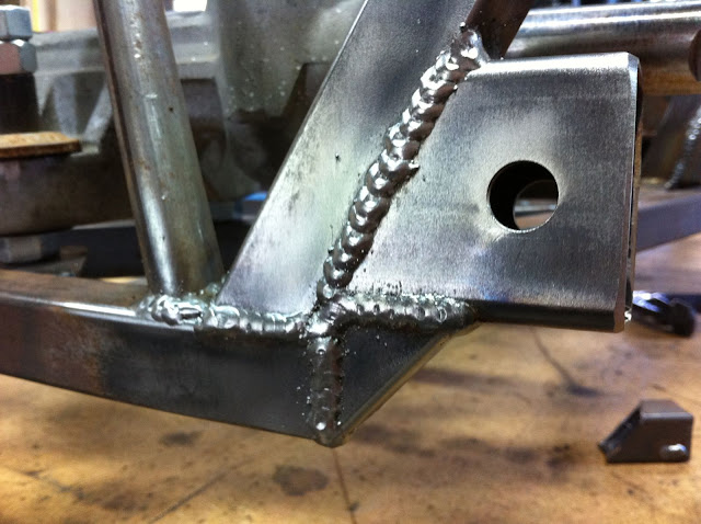
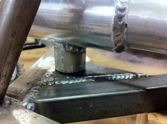
Pickup point welding
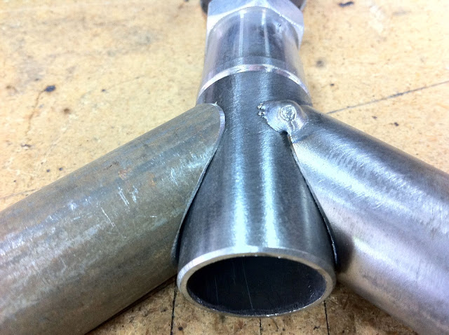
Pickup point weld penetration
Upper control arm fishmouth fit-up
Front lower pickup point with diagonal brace doubling as a cap for the lower tube
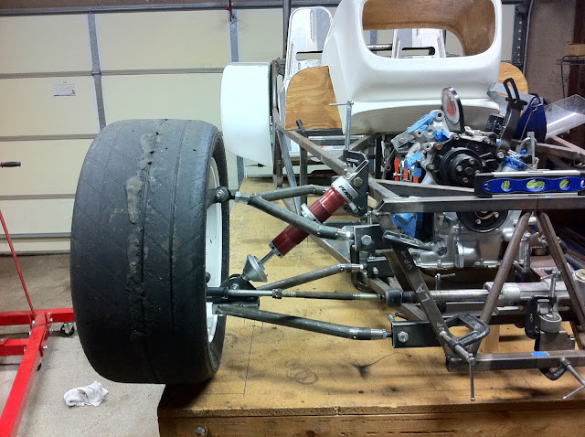
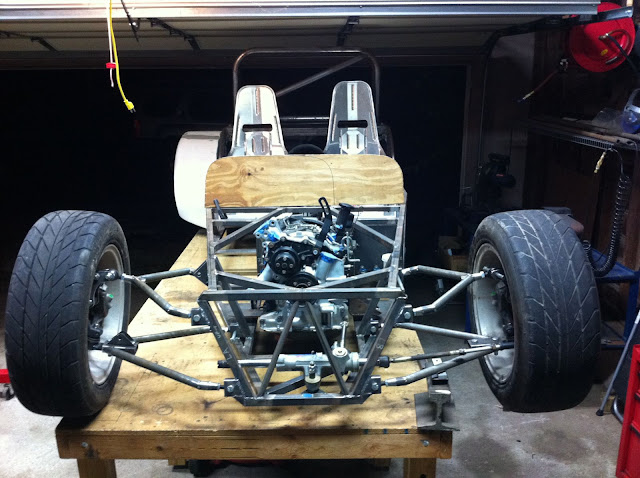
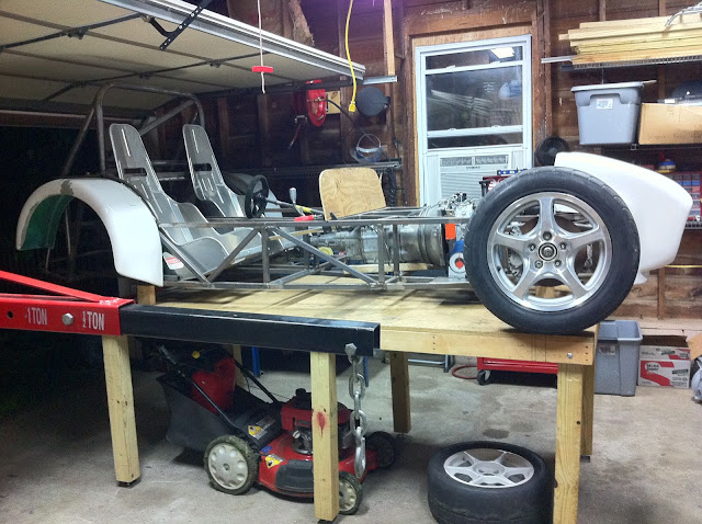
TWO WHEELS INSTALLED (not the wheels I'm using, WAY too tall, but had them lying around the shop so I grabbed them to try out
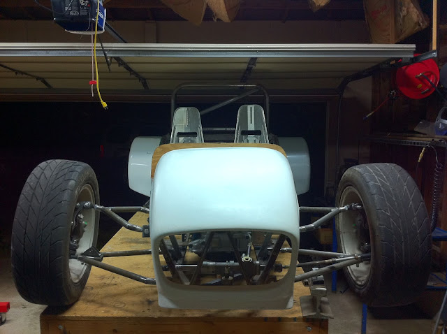
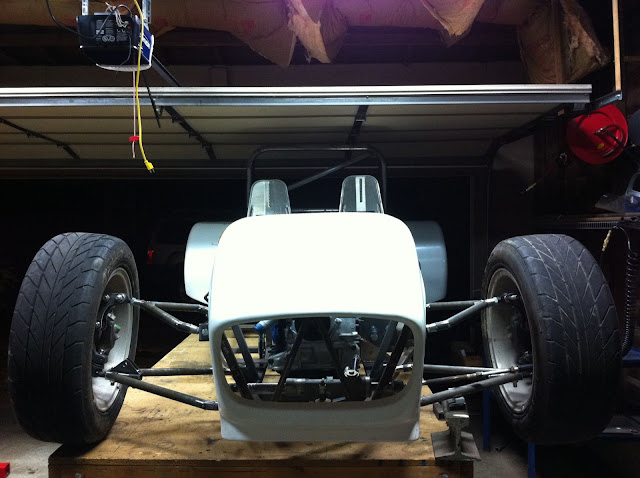
Nosecone radiator opening cut out and mocked up
It's a mean looking sucker!
I guess it's about time to make a real scuttle?
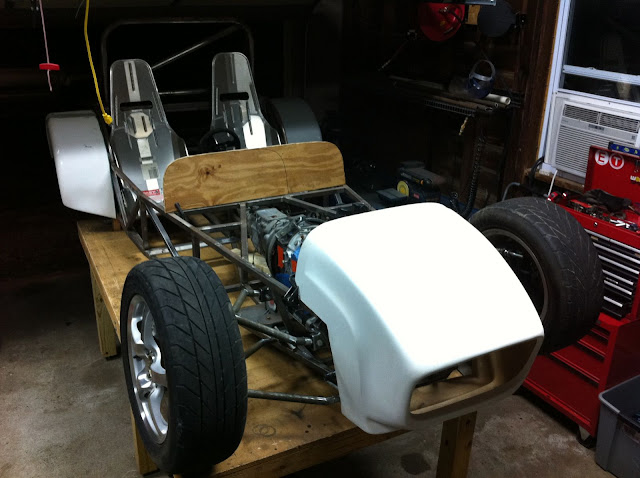
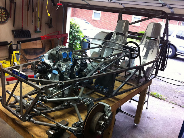
Side view, looks so cool with the wheels stretched out to the corners
_________________ -Emile Scratch building an IRS, RX-7 based book chassis @ myBuild Log
Joined: December 21, 2006, 2:30 pm Posts: 337 Location: Louisville, KY
More progress this week.
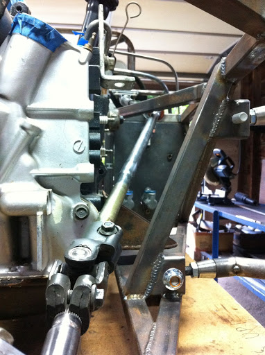
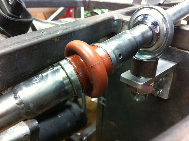
Steering column fabrication complete. I adapted a Honda S2000 steering rack and factory u-joint to a mil-spec 3/4" u joint just in front of the driver's footwell, then to a *gasp* collapsable section taken from a chevy minivan (I replaced one at work due to a common issue with the u-joints loosening, I didn't use the u-joint from the Chevy, that went straight in the garbage), then to a Spa quick release unit.
Steering column routing through engine compartment
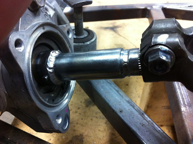
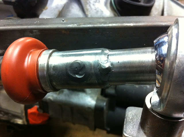
Stock Honda pinion gear shortened to make room for oil cooler fitting coming off the engine
Mil-spec 3/4" u-joint, used commonly in open-wheel single seaters. 3/4" rodend used as a support bearing in the engine compartment due to the high exhaust temperatures from the rotary engine.
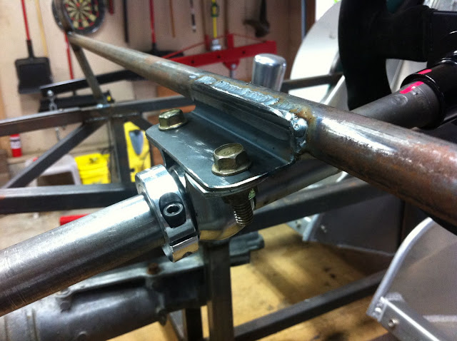
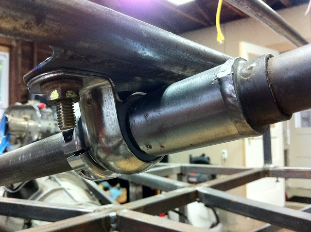
Bracket I made to attach the common Grainger-sourced bearing unit. 1" ID delrin (?) bearing clamped by stainless steel brackets. Keen eyes will notice the new dash framework I fabbed this weekend. 1" ID aluminum split collar sourced from JEGS to keep the collapsable column from self-adjusting while driving.
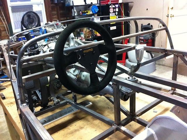
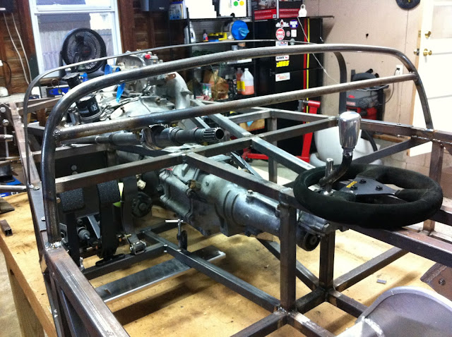
Can't remember the wheel size off the top of my head, but it's small enough to give me very precise, quick steering response, as well as giving me plenty of room to saw at the wheel without hitting my elbows on the sides or hitting my thighs.
Steering wheel removed.
Full view of steering column as well as new dash/scuttle framework beginning to take shape. Scuttle will be similar to Jeff's R1-powered build, steel frame with an aluminum skin. And it's detachable.
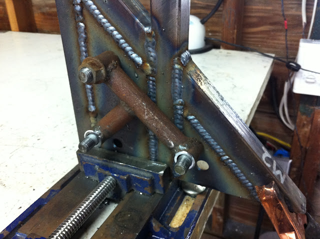
Every joint is a press-fit with a perimeter and plug weld.
More close-ups of the welding.
Another view of the main support bearing under the dash. This one is made of delrin since it won't be subjected to engine bay heat like the other.
Another steering column view.
Also made a bit more progress on the pedal layout. This setup should work, even with my work shoes (essentially low-top hiking boot) just in case I wanna drive it to work some time!
_________________ -Emile Scratch building an IRS, RX-7 based book chassis @ myBuild Log
Joined: July 17, 2008, 9:11 am Posts: 6416 Location: West Chicago,IL
Glad to see more progress.
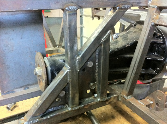
One comment about your motor mount. It looks like your RH mount is a 1/4" plate ??
I had to beef up my RH mount due to it bending like a pretzle. These torque-monster rotary engines can do some damage. Mine design was similar to yours but not exactly. You may want to take a look as I just updated my build showing my improved design.
Chuck
_________________ Chuck.
“Any suspension will work if you don’t let it.” - Colin Chapman
Joined: December 21, 2006, 2:30 pm Posts: 337 Location: Louisville, KY
rx7locost wrote:
Glad to see more progress.
One comment about your motor mount. It looks like your RH mount is a 1/4" plate ??
I had to beef up my RH mount due to it bending like a pretzle. These torque-monster rotary engines can do some damage. Mine design was similar to yours but not exactly. You may want to take a look as I just updated my build showing my improved design.
Chuck
Chuck,
Thanks for the heads up. It's buried somewhere in my build log but I'll say it again. The RH mount is not in it's final spec. I wanted to fab the exhaust first to see how much room I'll have to beef-up the motor mount. But I appreciate you looking out for me! I'm also interested to see how you modify yours, I'll go check that out now.
-Emile
_________________ -Emile Scratch building an IRS, RX-7 based book chassis @ myBuild Log
Joined: September 25, 2008, 6:13 pm Posts: 468 Location: Los Angeles, CA
great penetration on those welds. fantastic to see someone checking the back sides of their welds. However, be careful of spot welding with a mig torch as you create mini stress risers and far less penetration at the edges of each spot. I don't think you'll have a problem with that implementation but it's good practice just the same.
Joined: December 21, 2006, 2:30 pm Posts: 337 Location: Louisville, KY
A little more progress to show.
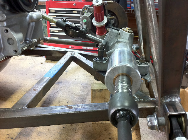
Finally finished the steering rack and tie rod extensions and installed everything. I finally have front suspension that steers!! WooHoo!
This is the susp at full droop. I just need to decide on spring rates and I'll have a roller!
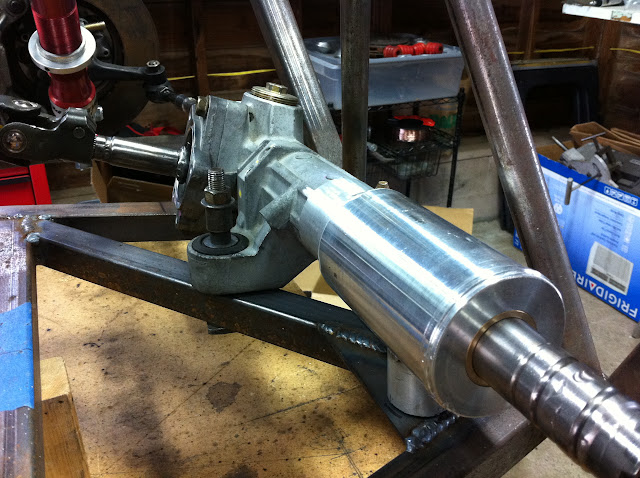
Details of the piece I had machined by a local guy. It serves a few purposes, 1) gives me a place to mount the stock S2000 boot, 2) I've added a simple brass bushing to support the rack out as far as possible and to limit travel, 3) gives me a place to add a simple threaded boss to mount from below on the passenger side.
Another view of the machined portion of the rack housing that I added.
The threaded boss welded to the bottom of the rack housing and a simple plate welded to the existing tube in the chassis for the other side's mount
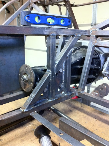
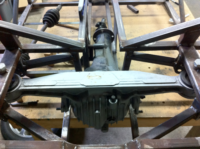
I changed the angle of the diff from level to -2 degrees to lessen the angle on the short driveshaft and to match the 2 degrees tail down on the engine/transmission. Here's the finished product welded off the car. This is the diff side
And here's the seat side
And installed in the chassis
Another angle
I had to chop the center section out there, I'll make a bolt-in brace to take it's place
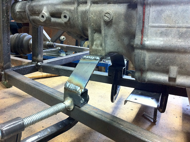
Okay, time to make a transmission mount! Started by setting the transmission at the perfect angle. Then cut a couple sections of square tubing and welded some fine thread 1/2" nuts in them.
Welded nuts
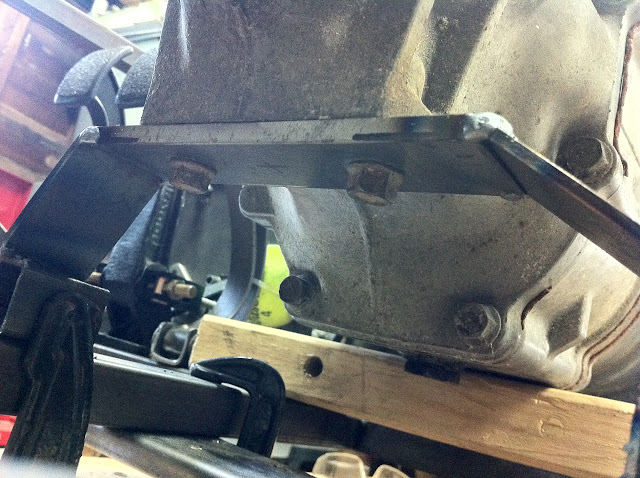
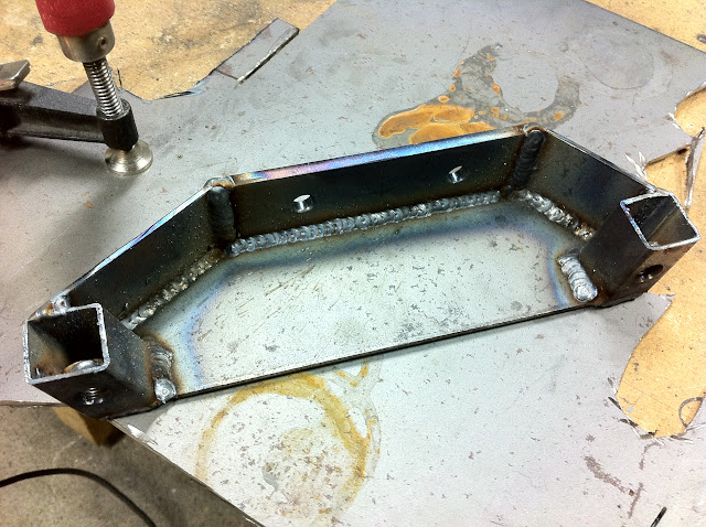
I cut a 1/4" plate to match the stock trans mount bolt pattern, then bridged the gap to the square tubing with some 1/8" plate
I had to keep in mind I'd need to be able to access these two bolts from below if I ever wanted to get this thing out again!
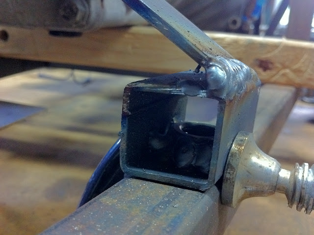
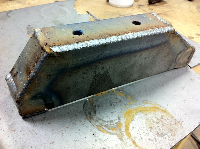
So I cut two pieces to "box" in the sides and fully welded them inside and out
This thing should be a lot stronger than it needs to be...
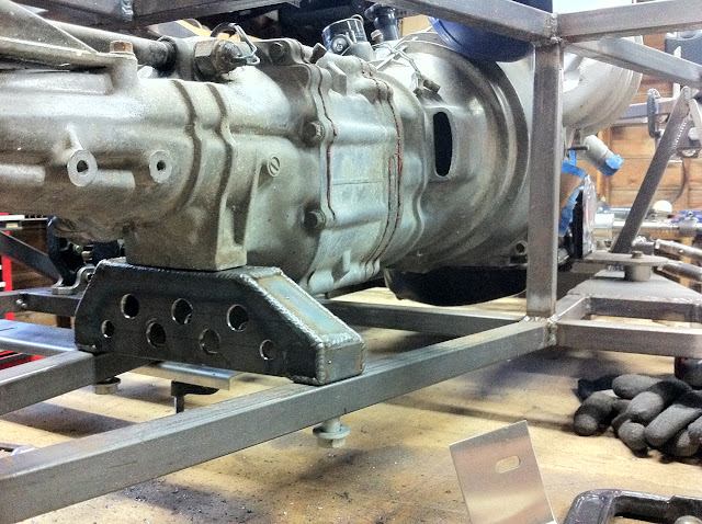
...So I decided to add some lightness...
I'm pretty happy with how it came out. It mounts with four bolts from underneath. I just need to "sleeve" the frame where the bolts pass through, I'll have to do that the next time I flip it over.
_________________ -Emile Scratch building an IRS, RX-7 based book chassis @ myBuild Log
Joined: February 20, 2006, 11:18 am Posts: 3186 Location: Lexington, KY
erturbo wrote:
I had to chop the center section out there, I'll make a bolt-in brace to take it's place
Hmm...I don't like that. I'd be real tempted to weld that back in and find another way to get the diff in and out. I'm no engineer, but I'd guess you're loosing a LOT of torsional rigidity with that leg missing, from the rear bulkhead panel rigidity and the tunnel rigidity.
If you stick with a bolt-in solution, try do design it so it can't develop slop at the bolt holes.
-dave
ps. I need to get up there and visit...
_________________ ...nowadays people are so intellectually lazy and lethargic that they can't build ANYTHING with their hands. They'll spend hours watching whiny people marooned on an island, but won't spend a second adding anything to the world. -weconway Visit my [Locost 7 build log]
Joined: July 17, 2008, 9:11 am Posts: 6416 Location: West Chicago,IL
Looks like you are making progress.
I am told it is bad practice to hard-mount on point while using rubber mounts on the other 2, or vice versa. It puts a lot of stress on the hard mount end. This goes for both you engine and your diff. you're mounting the RX diff up from below like I did. Check out my build, I didn't need to cut out that section of frame. If you decide to go further with your setup, consider that no only do you have the frame section, but the metal panel that will eventually be mounted to it.
Keep on moving forward
_________________ Chuck.
“Any suspension will work if you don’t let it.” - Colin Chapman
Joined: December 21, 2006, 2:30 pm Posts: 337 Location: Louisville, KY
dhempy wrote:
Hmm...I don't like that. I'd be real tempted to weld that back in and find another way to get the diff in and out. I'm no engineer, but I'd guess you're loosing a LOT of torsional rigidity with that leg missing, from the rear bulkhead panel rigidity and the tunnel rigidity.
If you stick with a bolt-in solution, try do design it so it can't develop slop at the bolt holes.
-dave
ps. I need to get up there and visit...
Yes, Dave, you DO need to get up here, though I understand you have your hands full recently
I'm kinda stumped on what else I could do. Short of cutting one of the arms off of the diff and somehow making it a bolt-on affair, I don't know what to do.
That being said, when I cut that section out with my sawzall, I had the weight of the diff, engine/trans, rear suspension all bolted in the chassis which was sitting on sections of 2x4 at each corner. And the sawzall cut through without ever binding up, so that tells me that section is supported well enough by the rest of the frame and that a bolt-in brace will probably be fine.
rx7locost wrote:
I am told it is bad practice to hard-mount on point while using rubber mounts on the other 2, or vice versa. It puts a lot of stress on the hard mount end. This goes for both you engine and your diff. you're mounting the RX diff up from below like I did. Check out my build, I didn't need to cut out that section of frame. If you decide to go further with your setup, consider that no only do you have the frame section, but the metal panel that will eventually be mounted to it.
Keep on moving forward
Chuck,
As always I appreciate you keeping an eye on me I have intended to either fill the stock rubber bushing in the diff with some sort of poly resin or just replace them with an aluminum bushing. Either way the whole thing will be solid mounted, not just the front. As for the engine mounts, there isn't any rubber in my front motor mounts either.
And as for the panel behind the seats I was either thinking of making the whole thing bolt-in, or having a removable panel above the trans tunnel for diff removal.
_________________ -Emile Scratch building an IRS, RX-7 based book chassis @ myBuild Log
Users browsing this forum: No registered users and 37 guests
You cannot post new topics in this forum You cannot reply to topics in this forum You cannot edit your posts in this forum You cannot delete your posts in this forum You cannot post attachments in this forum