2/15/12 - Did work, son
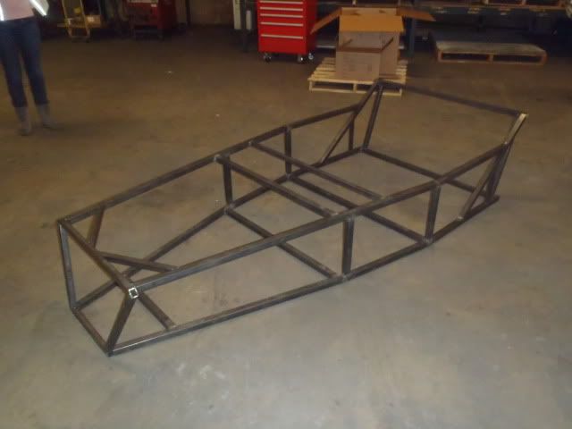
Got one of the guys in manufacturing to stay after a couple hours today and get the final welds put on the top and bottom halves, got them joined together. Came out amazing, less than 1/8" of flex throughout, spot on in offsets on the front end (hopefully get the front put together toward the end of the week). Anyway, enough of the boring [PooPoo] - PICTURES
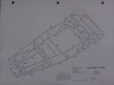
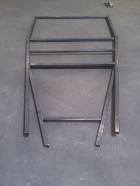
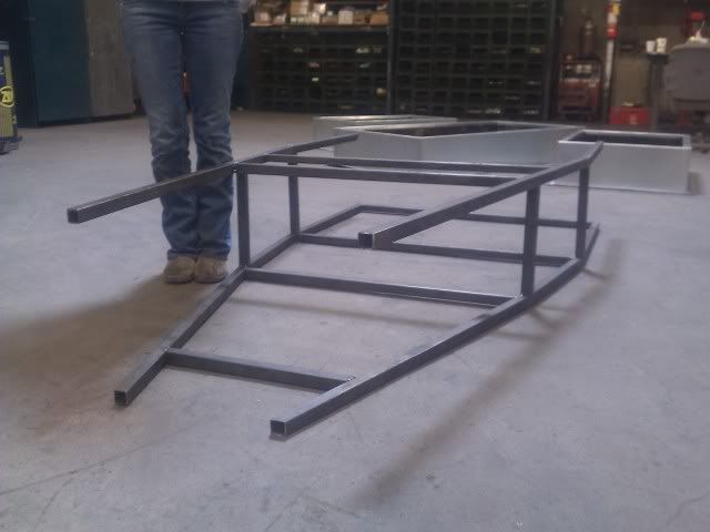
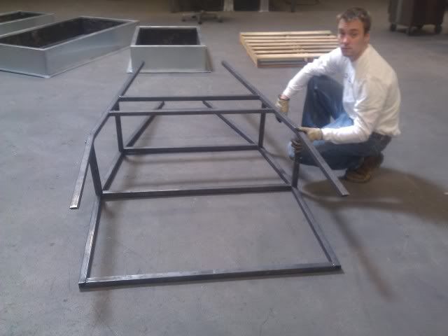
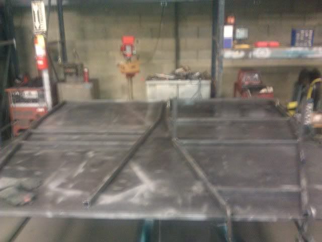
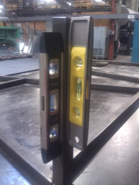
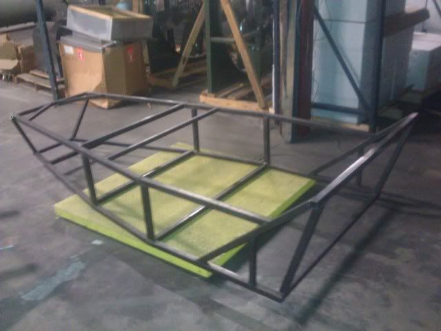
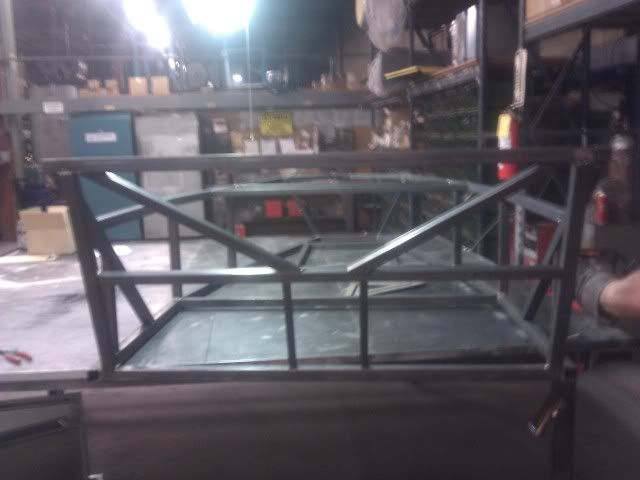
Build Table
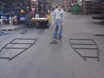
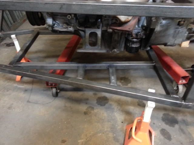
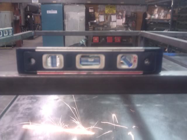
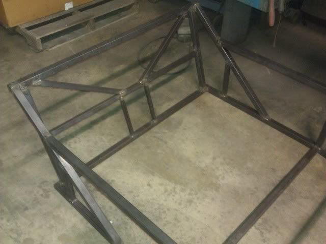
Leveling out the H beams (connect top and bottom frame halves)
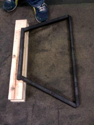
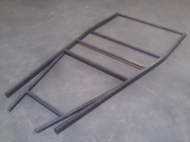
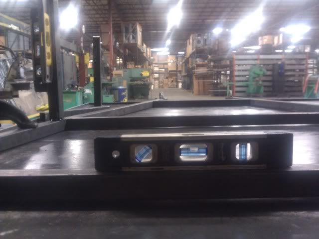
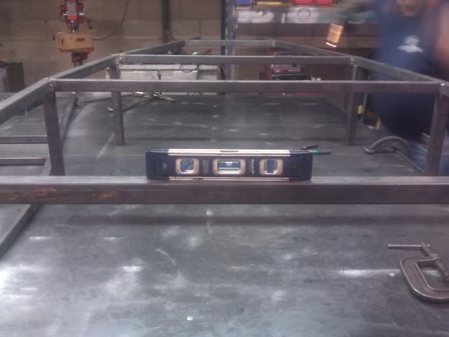
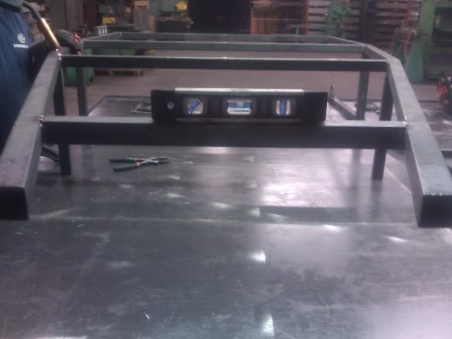
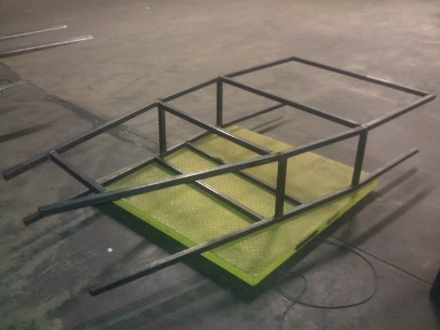
After the H Beams are welded on, turned the piece upside down to measure how level our cuts are...pretty spot on
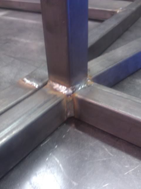
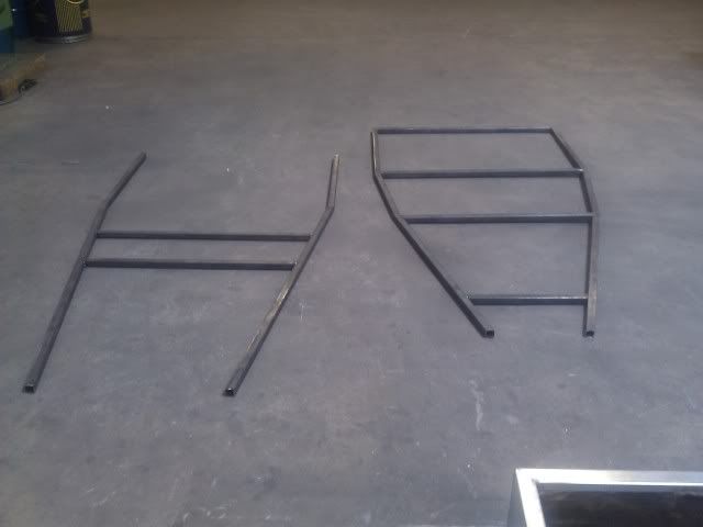
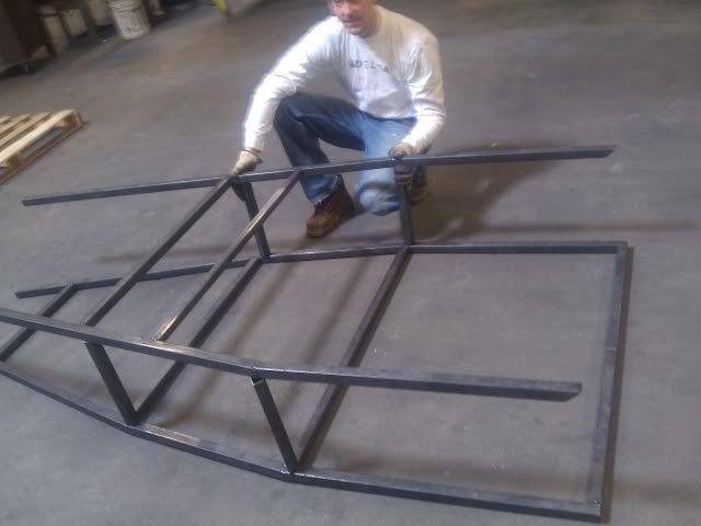
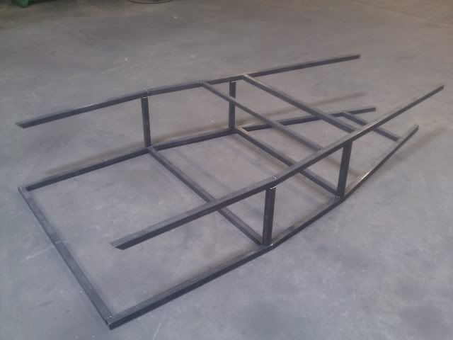
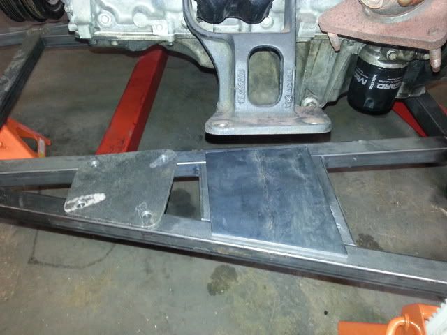
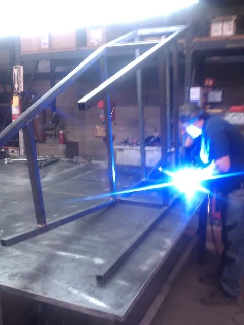
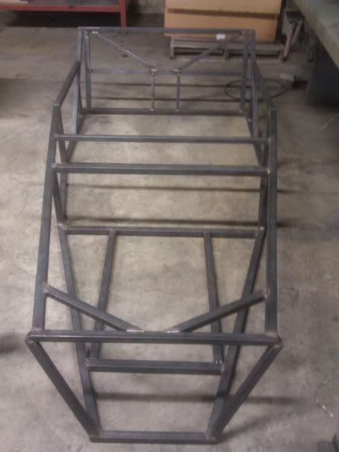
Finally, welded them together
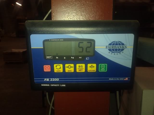
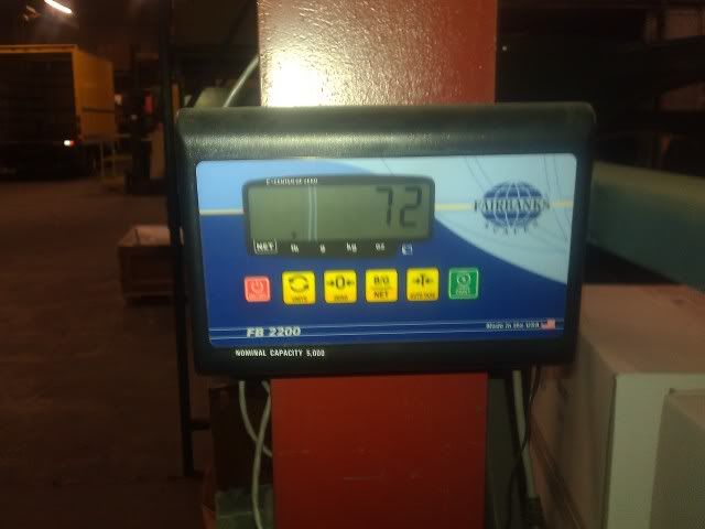
This portion of the frame weighs in at 52lbs
2/17/12
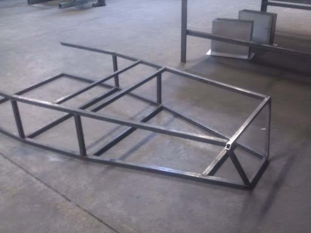
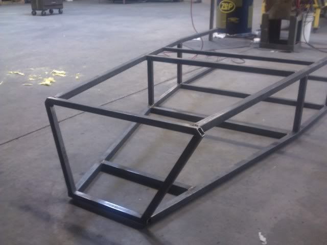
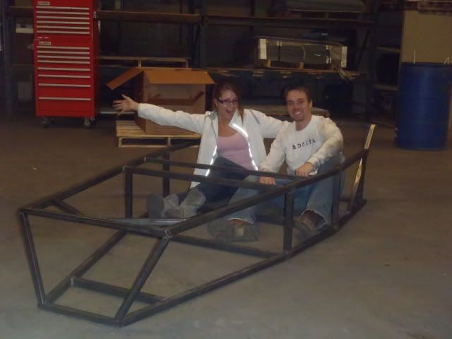
Went back during lunch and got the front end tacked together, then mounted on the frame. these pieces were some of the hardest to cut, the compound cuts could only be made in two dimensions on our chop saw, so i had to draw it out and hand grind the third dimension. It took Nicad and I the better part of two hours to get the eight pieces (four per car) cut and angled correctly...looks like it was worth it. The front end is a little wider than the book plans, but I'm thinking that may be a positive trade off as it will allow more more side to side width for the large V8 and will also help widen the front track. No pictures of the process, I only had 30-45 minutes to get things together before manufacturing got back from lunch and snagged the welder back.
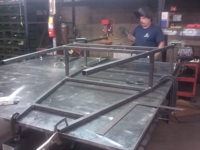
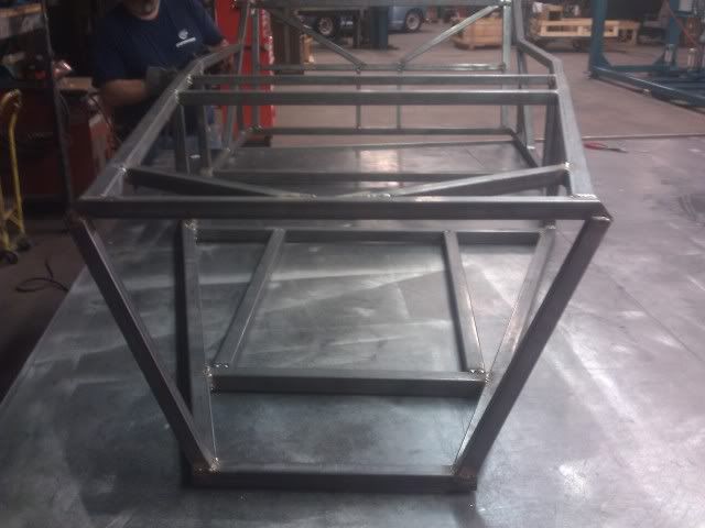
2/18/12 - FRAMES DONE
still has some more bracing to go, but the main portions of the frame are done. Tacked together the rear end this afternoon (bigest PITA this far). Weighed in at 72 lbs, actually a little less than what i was expecting.
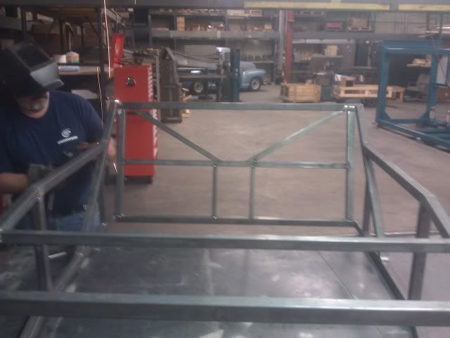
2/23/12
Frame exoskeleton is completely finished and welded up. The only two pieces that aren't fully welded in are the two G rails, the rails that hold the motor up. I figure if I need to modify the width in these for oil pan clearance or better lineup with the motor mounts, I can easily break the tacks move them around. Frame's weight up until this point is 84 lbs.
continued
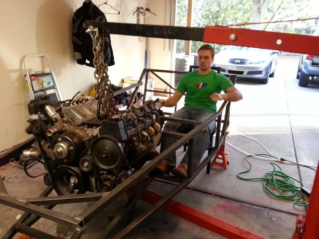
8/10/12
enter the mullet mobile, the first move i've made towards this project in almost 6 months. Fully running donor car, couldn't have asked for a better opportunity with one exception, which I'll elaborate on shortly. Interior is [PooPoo], don't know that I'll be able to recoup much cost parting that out, but he's got aftermarket wheels (with a little bit of tread left on the tires...for now) and aftermarket stereo, which I'll probably rip out and sell. Tranny shifts well, has new clutch. Other than wheels and tires, this thing is 100% stock with 110,062 miles on. Perfect.
The negative...engine has a tick. Not sure what's going on with it right now, as it exhibits symptoms of multiple things. I'll get it looked this next week, hopefully it's something as simple as lifter knock or a bad exhaust manifold gasket. Even if it's rod knock, the motor is still running strong, so hopefully it'll be an easy fix. Took it on a test drive, has solid power throughout the rev band. Just. a. tick.
I picked up the entire running car for less than the cost of the drivetrain package we've been looking for, so even if I break even by selling off the wheels and shell to fix the motor, I'm still happy with the purchase. And it let's me move on, as I'm at the point on the frame where I can't go any further without having the motor / tranny for mock. I'll probably get the motor looked at, drive the T-top mullet mobile while I tinker on the frame, then swap it all over.

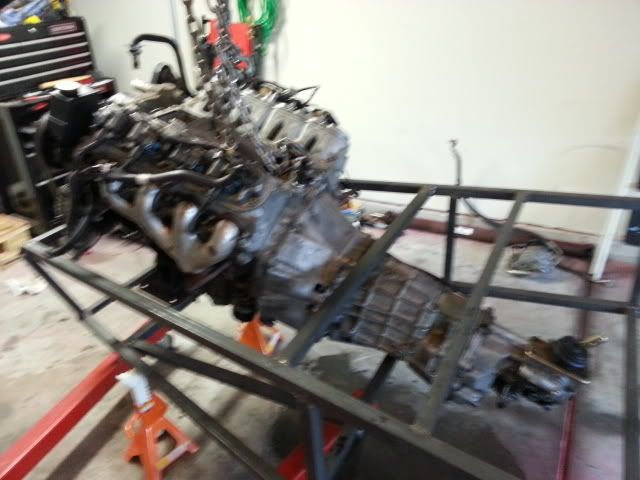
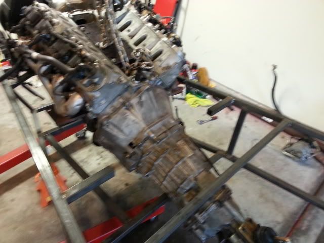
8/15/12
crap, so i just looked up the dimensions, then measured the frame, then realized i'm screwed. The dimension from the front of the crank pulley to the back of the bell housing is just over 35". I have about 38" to play with, but I think I'm going to need the space up front, and I need to mount the entire assembly where the shifter is at the point I want it.
[url="http://www.locostusa.com/forums/viewtopic.php?f=35&t=2432&start=15"]I checked out Phil's LS1 build thread (great source for info, btw)[/url] to see how he got around this, he ended up hacking one of the main support bars and redoing it. He didn't note this via text, so I never even picked up on it, but when looking at his pictures to see how he did it I discovered this one (hope this works):

check out the support brace where the tranny bell housing sits...[Fornicate]. Phil actually raises this bar, but I think i'm just going to relocate it. This is why they say don't start the frame w/out the drive train...