I wrote up an article on locating the subframe, engine, tranny and driveshaft last year as I was doing it. It's written from the perspective of a dummy's guide, for someone who doesn't really know what he's doing and likes a lot of hand-holding and over-analysis. (BTW, that's a description of ME, not you!)
Re-reading it now, it seems a bit over-the-top fussy and arguably anal. In fact, there's a few points on which I now disagree with the author.

I also never quite finished it, as you'll find placeholders where actual measurements and math should go. I can flesh it out if you like, but I think you'll see where I was headed. If folks think this is worthwhile, PM me and I'll finish it up some time and post it somewhere more appropriate. I have all those numbers and calculations around here somewhere, or can measure them again. Otherwise, enjoy or delete!
-dave
X axis - measures left and right of centerline
Y axis - measures distance from front to rear
Z axis - measures from ground to sky
Assuming: tranny output shaft centered in car
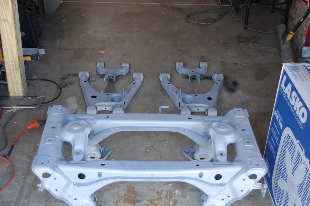
Assuming: we're using the intact Miata subframe and rear suspension, with the brake rotors centered on the car. I suspect a lot of this could apply to other IRS or live axle designs, as well.
Assuming: the driveshaft length between U-joints is 27.5". That's what my +442 worked out to need. Anything within about 10% of that (25" - 30") won't affect this article substantially.
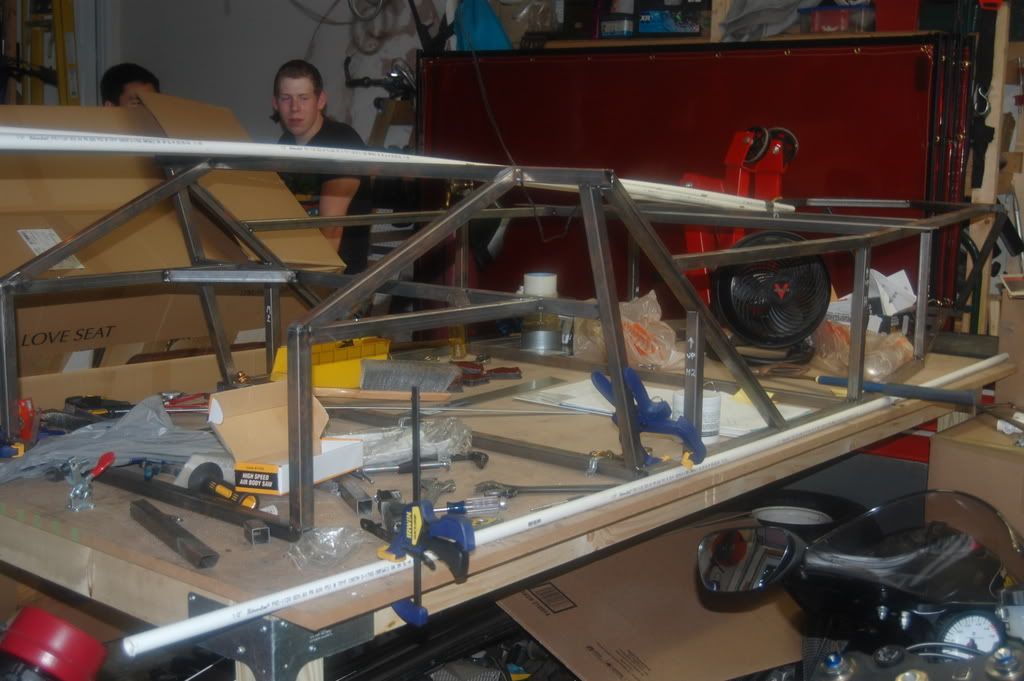
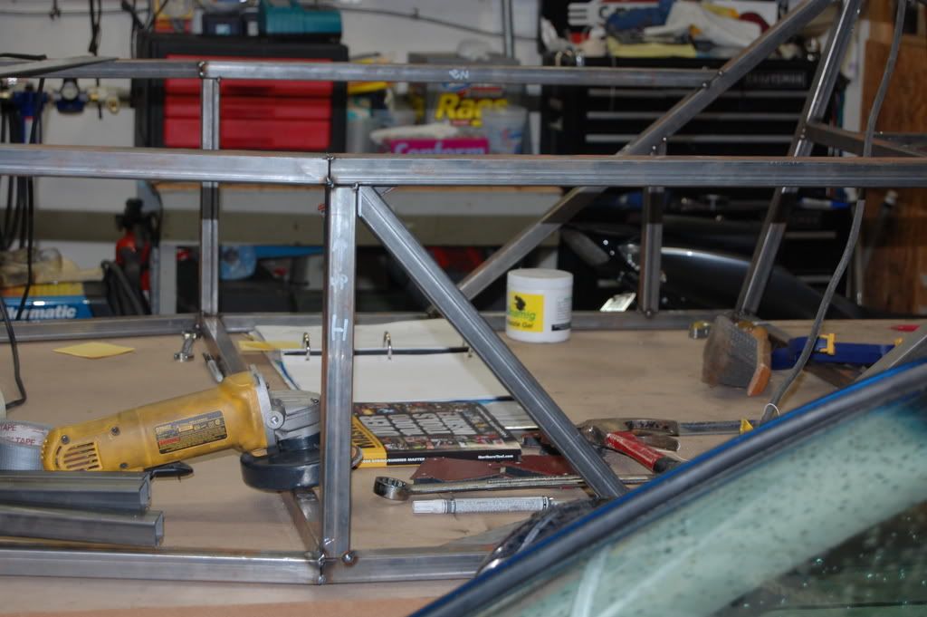
Put the frame on jack stands and level the frame on X and Y axes. Carefully mark the centerline of the car on every tube that crosses it. Use a yellow or white paint pen so you can easily eye-ball from the other end of the car. This will let you stand back and center components in the "big picture" very easily and accurately, within 1/8" or better. If you want to scribe a more precise centerline for the detail work, that's fine, but don't obsess about it.
REAR END:
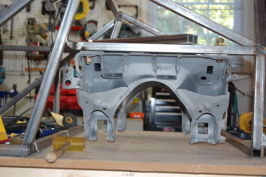
Put a piece of plywood across two drywall buckets, just behind the rear bulkhead. Shim up the plywood so its top is in plane with the top of the lower frame rails. Later on, the plywood will be replaced with 1" tubes to support the subframe.
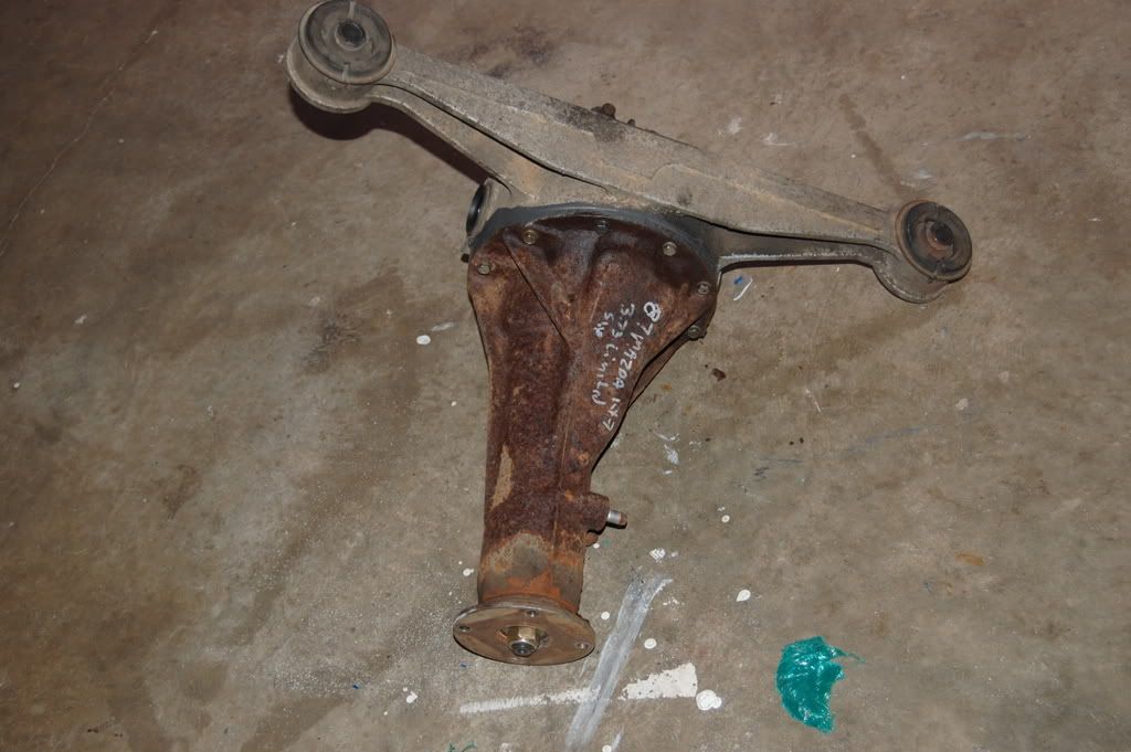
Put the subframe (with brake rotors, but no wheels) on the plywood, so it almost touches the bulkhead. Make sure the lower A-arms are symetrical. If the plywood supports both of them at level, that's probably ideal. Adjust all four A-arm adjustment cams to center and tighten.
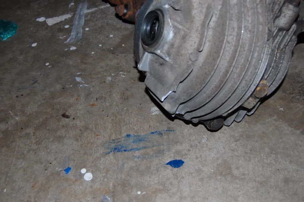
Take two long (8' or so) pieces of tube from your stock pile. Confirm they are straight. Clamp one to each brake rotor, so they extend up near the footwells. Measure from the car's centerline to these tubes and move the subframe until they're equal. Also measure from the tubes to the side rails at the rear bulkhead and make sure they're equal. Go ahead and mark the center of the subframe with a paint pen, based on the rotors. Note that the differential pinion will NOT be centered, and that's OK. Check that the frame is level, and level the subframe with shims. The top of the subframe is probably good enough to level on, but use the imaginary line between the A-arm adjustment cams if you're particularly fussy.
Repeat the above adjustments and measurements until the planets align and your soul is at peace.
It may be that you can't get everything to align at the same time. This might mean something is out of square. Figure out what, and decide to fix it or compromise. I don't have enough experience to recommend an acceptable tolerance to shoot for...perhaps someone else can chime in? I got everything simultaneously within 1/8", and figured that's as good as I could.
Weld the subframe into place, using whatever framework you decide on. I hung it from above for now, holding off on the lower rails. This will let you easily unbolt and remove the subframe for later frame work. Alternately, you could fully weld the subframe, without the option of unbolting it later. If you have removable lower rails (I'm not planning on it), this isn't an issue. I went ahead and finish-welded the subframe mount, as there is going to be at least 100 pounds hanging from it, and I didn't trust tacks for that. Remove the buckets and plywood...you'll need them later.
Your differential location is now set in stone. Eliminating that variable simplifies locating the engine.
ENGINE/TRANSMISSION:
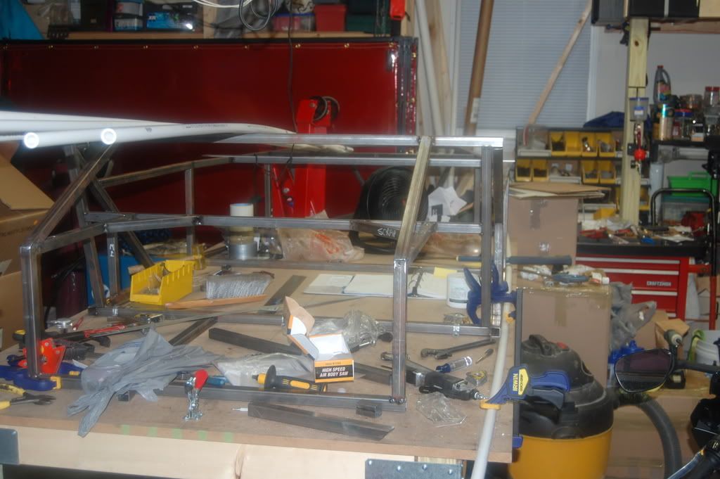
Clamp a 48" drywall square (or similar straight edge) between tubes B1 and B2, (under the driveshaft), with one edge on the centerline. The long leg of the square should extend back under the diff.
With the Miata subframe centered (according to the brake rotors), the pinion center will fall Q.QQQ" inches right of center. If yours happens to be different, some assumptions here will be inaccurate.
The pitch (nose up/down) of the diff is not locked in yet...you can easily move it by hand. Temporarily hold the diff level (measure on the pinion face). A ratcheting strap from above makes this easy to tweak and will keep it there all day. Measure the vertical distance from the top of the lower rails to the center of the pinion. A sliding square (tri-square) and the drywall square on the lower tubes makes this easy. Measure from the *bottom* of the drywall square for maximum accuracy...although it probably doesn't matter too much. On mine, it came out Q.QQQ" above the rails. That came from resting the lowest points of the subframe on the plane defined by the top of the lower frame rails. (Actually, slightly higher than that, because I discovered later on that I goofed. Oh well.)
Drop the engine and tranny in the hole. You can't lower the engine enough, because the C tube is in the way. You can't go much further without cutting that tube, so you might as well get it over with. Get the engine/tranny as close as you can with the tube in the way. Make sure the engine is level from left to right. Hanging from the shop lift, it will probably list to the side. Setting it on blocks under the oil pan will square it up pretty well. Keep some tension on the lift chains for safety.
Figure out where the vertical inboard H tubes need to go. The clutch arm is in the way, so I moved the right H tube over to clear it by 3/8" or so. Read ahead and get a fair idea how far back the engine will be. You probably can't get the engine that far back yet, so project forward to see how much the left H tube will need to clear the bell housing. I considered angling the H tubes to optimize clearance, but I figured I'd regret it later when putting the sheet in.
Tack those tubes into place, and then cut the C tube. Everything gets easier from here.
Shorten your stack of blocks under the oil pan to get the engine at ride height, relative to the frame. Ignore the ground...decide how low you want it to hang below the rails.
Let's say you're shooting for 5" of clearance between the road and the lower frame rails, and you want 3" of clearance below the oil pan. That means you need the pan to be 2" below the rails. Side note - To lower the CG of the car, *raise* the engine in the chassis, and then lower the chassis. Counter-intuitive, but this lets you lower the chassis without giving up your 3" of oil pan clearance. If you went the other way, and hung the engine 4" below the frame, you'd need to jack your chassis up to 7" inches or so, ultimately raising the CG and looking like a 4x4, too boot. I'm nowhere close to making a hood yet, so I'm not sure what to shoot for there. I'm curious to hear how far other Miata builders hang the pan below the frame, and how that panned out (punny!) when putting the hood in place.
Anyway, so you've got the engine sitting on a block, vertically where you want it in the car. Leave the shop crane hooked up for safety, and to lighten the load when shoving the engine around.
If you haven't welded floor in yet, set a drywall bucket where the driver's seat goes. Put a seat on it, or a reasonably facsimile of one if you don't have your seats yet. Adjust until your butt and back are sitting about where they will be when driving. If you're not sure, I'd put the pretend seat a bit forward. If you put it all the way back and later find the shifter is too close, there's no pushing the seat farther back, that's for sure!
This is when you're going to locate the engine on the Y axis (fore and aft), based on where the shifter falls under your hand. Pretend motor noises are allowed, if not encouraged, during this step. Use the lid of the drywall bucket as a steering wheel. You'll probably like the steering wheel and the shifter about the same distance from the seat back. That is, the shifter should be in the plane defined by the steering wheel. This well help your hand fall naturally to the shifter, instead of having to reach for it. With my own skeletal geometry (the only constant in this entire equation!), the shifter pivot ended up Q.QQQ" behind the B2 tube, which put the bell housing Q.QQQ" inches in front of the C tube. Don't worry about the steering wheel location...that was just a visualization tool.
At this point, get your small floor jack and put it under the tail end of the tranny. Jack it up to level. To find level, put a bubble level on the engine head (not the valve cover), starter, or the PPF mating surface. That last option is easiest. Measure the height of the output shaft center above the lower rails, just as you did for the differential pinion. This isn't where it's going to end up, but it makes for some easy measurements to figure out where it will go.
At this point, you can measure the length of your driveshaft, center-to-center between the U-joints. Leave out the length of the pinion flange and the yoke beyond the U-joints. I don't think the yoke will be telescoping any in this install, but I gave it 1" of room all the same...that still leaves about 3" of engaged splines. Mine came out to 27.5" between the U-joints. Don't use my number...yours will be different!
I've Googled advice on driveshaft angle. From what I've read, you can go up to 3 degrees pretty comfortably. It sounds like you don't want 0 degrees. I'm not real clear if 3 degrees is the ideal, or just the max. Anybody have an opinion on this? My target is 1 to 3 degrees, favoring lower end of the range. Note that this is total angle, not just the vertical angle. The driveshaft can't tell the difference between vertical and horizontal angles.
If you have the yoke and the pinion at exactly the same height, the tranny centered, and the differential pinion Q.QQQ" to the right, you'll have a Q.Q degree angle.
If you raise or lower the yoke Q.QQQ" , you'll have a 3 degree angle, taking both X and Z offsets into consideration.
So this is your target zone: get the tranny within Q.QQQ" vertically of the diff. If you do that, your driveshaft angle should be good. (based on all the assumptions listed above) That's a pretty easy target to hit.
Note that you have to tilt the tranny quite a bit to change the angle... +/- Q.QQQ" runs you from -3 to +3 degrees. To get the same range of angles tilting the diff only requires +/- Q.QQQ" of pinion travel. This makes our job easy: consider the diff to be fixed in location (both X and Y), and set the tranny based on that.
If you can reach the little floor jack from the driver's seat, that's perfect. Adjust the height of the shifter to the middle of the target range. You are pivoting the engine on the blocks, not raising/lowering the entire engine.
most