LocostUSA.com

Learning how to build Lotus Seven replicas...together!
It is currently April 18, 2024, 11:04 pm

All times are UTC - 5 hours [ DST ]


Post new topic Reply to topic  [ 227 posts ]  Go to page Previous  1 ... 5, 6, 7, 8, 9, 10, 11 ... 16  Next
Author Message
 Post subject:
PostPosted: May 1, 2006, 10:40 am 
Offline
Mid-Engined Maniac

Joined: April 23, 2006, 8:26 pm
Posts: 6419
Location: SoCal
Yeah moving the pivot up and outward would take care of that.

About the rear bracing, is there a diagonal below the differential? Can't tell from the pictures. I mean the open panel directly below it. It should have something, a steel plate if not diagonals.

_________________
Midlana book: Build this mid-engine Locost!, http://midlana.com/stuff/book/
Kimini book: Designing mid-engine cars using FWD drivetrains
Both available from https://www.lulu.com/


Top
 Profile  
Reply with quote  
 Post subject:
PostPosted: May 1, 2006, 10:42 am 
By turned around backward I assume you mean you swaped the right and left side to put your steering arms up front?

If that's the case, your going to have some real trouble as your Ackerman will now be backward (ie. your outer wheel will turn sharper than you inner).

Moving the tie rod on top won't change that at all.


Top
  
Reply with quote  
 Post subject:
PostPosted: May 1, 2006, 11:14 am 
If it puts the tie rod end in line with the kingpin, it will return the geometry back to zero ackerman. On these knuckles, the steering arm is set at an angle. Putting the rod on top moves it outboard enough that it will set it back to no ackerman. Ackerman will then be dialed in by moving the rack back.


Top
  
Reply with quote  
 Post subject:
PostPosted: May 1, 2006, 11:18 am 
kb58 wrote:
Yeah moving the pivot up and outward would take care of that.

About the rear bracing, is there a diagonal below the differential? Can't tell from the pictures. I mean the open panel directly below it. It should have something, a steel plate if not diagonals.


No diagonal below the differential just yet. I will probably go with a removable steel plate there. Right now, that opening on the bottom is the only way to get the diff out of the "cage". So, I figure I can build a plate that will unbolt to allow swapping the chunk out if needed.


Top
  
Reply with quote  
 Post subject:
PostPosted: May 1, 2006, 12:47 pm 
Offline
Mid-Engined Maniac

Joined: April 23, 2006, 8:26 pm
Posts: 6419
Location: SoCal
datz510 wrote:

No diagonal below the differential just yet. I will probably go with a removable steel plate there. Right now, that opening on the bottom is the only way to get the diff out of the "cage". So, I figure I can build a plate that will unbolt to allow swapping the chunk out if needed.


Okay good. As it is there's nothing preventing the lower-rear a-arm mounts from shifting sideways under cornering load. Make sure the bolts holding the plate in are interference fit else the plate won't restrain movement.

_________________
Midlana book: Build this mid-engine Locost!, http://midlana.com/stuff/book/
Kimini book: Designing mid-engine cars using FWD drivetrains
Both available from https://www.lulu.com/


Top
 Profile  
Reply with quote  
 Post subject:
PostPosted: May 1, 2006, 12:59 pm 
Last night, I ordered a bunch of parts to help finish the car..

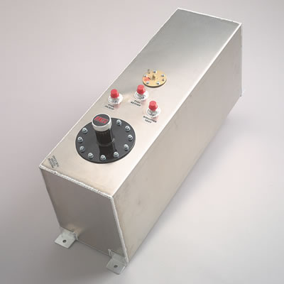
Ordered one of these RCI aluminum fuel cells. This cell is a 15 gal unit, has 0-90ohm fuel level sender, feed and return lines and can be set up for an external fill cap. Dimensions are 9" wide x 30" long x 12" high. I'll probably pick up some fuel cell foam to prevent sloshing at a later date.
Image

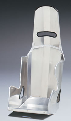
I researched the Porsche seats that I have and found that it was going to be more expensive to cover them than to just go with new racing seats. So, I ordered two Kirkey aluminum racing seats in a 17" width. They are nicely padded once the seat covers are installed.
Image

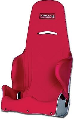
For these seats, I got two of these seat covers, but in black tweed:
Image

On to the pedals. I picked up one of these Wilwood clutch pedal assemblies:
Image

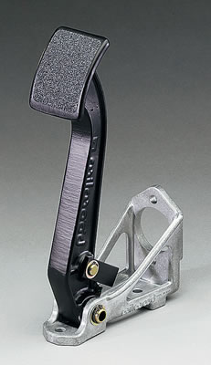
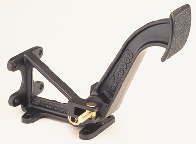
And a Wilwood dual master cylinder brake pedal:
Image

And a b!tchin' Woodward manual rack and pinion, as the Porsche rack doesnt look like it'll be reasonable to implement. I got the 2.38 in/turn ratio, so it should be decently quick.. I'd be interested to hear what ratio that others are using. 2.38 was the quickest rack they recommended for pavement use without power steering.
Image


Top
  
Reply with quote  
 Post subject:
PostPosted: May 1, 2006, 1:26 pm 
kb58 wrote:
datz510 wrote:

No diagonal below the differential just yet. I will probably go with a removable steel plate there. Right now, that opening on the bottom is the only way to get the diff out of the "cage". So, I figure I can build a plate that will unbolt to allow swapping the chunk out if needed.


Okay good. As it is there's nothing preventing the lower-rear a-arm mounts from shifting sideways under cornering load. Make sure the bolts holding the plate in are interference fit else the plate won't restrain movement.


Will do! Thanks for the advice. I may end up doing a flanged X frame or something of the sort under the diff. As long as whatever I put in is removable for access, I'll be happy with it.

I will need to reinforce the inner edges of the lower A arm mounts as well, as you can see from the photos, the lower mounts are welded on TOP of the lower diff cage members. I was thinking of mabye tying the frontmost lower mounts with diagonals into the intersection of member "O3" and the uprights next to the diff pinion flange.


Top
  
Reply with quote  
 Post subject:
PostPosted: May 1, 2006, 2:10 pm 
I don't see how moving the tie rod end from the bottom to the top moves it out any. It just flips it to the other side of the hole. Take a look at the spindles of a front steer car. You'll find that the steering arms angle outward instead of inward as on rear steer. And moving the rack location will have no effect on Ackerman. I think your going to find your wheels toe in when turned.


Top
  
Reply with quote  
 Post subject:
PostPosted: May 1, 2006, 2:20 pm 
Offline
Mid-Engined Maniac

Joined: April 23, 2006, 8:26 pm
Posts: 6419
Location: SoCal
He was concerned about kingpin offset, not Ackerman which a separate issue.

_________________
Midlana book: Build this mid-engine Locost!, http://midlana.com/stuff/book/
Kimini book: Designing mid-engine cars using FWD drivetrains
Both available from https://www.lulu.com/


Top
 Profile  
Reply with quote  
 Post subject:
PostPosted: May 1, 2006, 2:31 pm 
Paul, these knuckles have steering arms that have holes which are not perpendicular to the ground. They are angled, persay. This angle allows one to place the tie rod on top of the arm (which moves the rod end up and outward) and essentially eliminates the preset ackerman. I've measured it out and it sets the ackerman to zero if used in this way. I dont know if they designed the knuckles to allow this or what, but it looks like it should work, while at the same time setting up a nice tie rod alignment for the frontend.

Here is a photo of the knuckles. You can kindof see how they are angled in this pic:
Image


Here we go.. this pic shows it pretty well: You can see how the steering arm end is angled compared to the A arm. By putting the tie rod end on the top of this particular arm, it moves it up AND outward, which negates the preset Ackerman. The ackerman for my setup will then be dialed in via the rack placement.
Image


Top
  
Reply with quote  
 Post subject:
PostPosted: May 1, 2006, 2:43 pm 
PaulG wrote:
I don't see how moving the tie rod end from the bottom to the top moves it out any. It just flips it to the other side of the hole. Take a look at the spindles of a front steer car. You'll find that the steering arms angle outward instead of inward as on rear steer. And moving the rack location will have no effect on Ackerman. I think your going to find your wheels toe in when turned.


Moving the rack will absolutely affect ackerman. Moving the rack backwards closer to the wheel centerline increases ackerman angle.

Here is a good source:
http://www.stockcarproducts.com/steer12a.htm


Top
  
Reply with quote  
 Post subject:
PostPosted: May 1, 2006, 3:48 pm 
datz510 wrote:
PaulG wrote:
I don't see how moving the tie rod end from the bottom to the top moves it out any. It just flips it to the other side of the hole. Take a look at the spindles of a front steer car. You'll find that the steering arms angle outward instead of inward as on rear steer. And moving the rack location will have no effect on Ackerman. I think your going to find your wheels toe in when turned.


Moving the rack will absolutely affect ackerman. Moving the rack backwards closer to the wheel centerline increases ackerman angle.

Here is a good source:
http://www.stockcarproducts.com/steer12a.htm


Paul, I took another look at the geometry and you are right in that with zero ackerman to start, moving the rack will not have an effect. I went through and reread the soruce I posted and its apparant that you can move the rack to increase ackerman only after some ackerman angle has been established in the steering arms. So, I appologize.. I stand corrected.

So, I'll have to figure out how to solve this. Either come up with a way to get the tie rod ends outboard of the pivot axis or swap out knuckles to something that will be more suitable. I'd hate to have to redo my A arms though. Any ideas?

...If its not one problem, its another. I'll take a close look at the knuckle and whether or not I'll have any ackerman angle with the arrangement I was planning on. If I can get some angle with the current setup, moving the rack will help.


Top
  
Reply with quote  
 Post subject:
PostPosted: May 1, 2006, 3:57 pm 
Offline

Joined: August 16, 2005, 10:29 am
Posts: 1072
Location: Alberta, Canada
looking great. where did you get your bodywork from?


Top
 Profile  
Reply with quote  
 Post subject:
PostPosted: May 1, 2006, 4:09 pm 
Here is an interesting tidbit:

page 294 of John C. Dixon, "Tires, Suspension and Handling," SAE, 1996

"It is widely believed that aligning the steering arms so that their lines intersect at the rear axle will give the true Ackermann steering (the Jeantaud diagram). However, this is far from true; the actual Ackermann factor varies in a complex way with the arm angle, rack length, rack offset forward or rearward of the arm ends, whether rack is forward or rearward of the kingpins, and with the actual mean steer angle. Moving the rack forward or backward to change the tie-rod angles can be a useful way to adjust the Ackermann factor, the most important single variable being the angle between the tie-rod and the steering arm in plan view, the Ackermann factor being proportional to the deviation of this angle from 90°. With straight tie-rods, to obtain an Ackermann factor close to 1.0 may require the projected steering arm intersection point to be at about 60% of the distance to the rear axle."


Last edited by datz510 on May 1, 2006, 4:12 pm, edited 1 time in total.

Top
  
Reply with quote  
 Post subject:
PostPosted: May 1, 2006, 4:09 pm 
Offline
Mid-Engined Maniac

Joined: April 23, 2006, 8:26 pm
Posts: 6419
Location: SoCal
In the 60s and 70s it was common practice to heat the steering arms with a rosebud and bend them to where you want.

_________________
Midlana book: Build this mid-engine Locost!, http://midlana.com/stuff/book/
Kimini book: Designing mid-engine cars using FWD drivetrains
Both available from https://www.lulu.com/


Top
 Profile  
Reply with quote  
Display posts from previous:  Sort by  
Post new topic Reply to topic  [ 227 posts ]  Go to page Previous  1 ... 5, 6, 7, 8, 9, 10, 11 ... 16  Next

All times are UTC - 5 hours [ DST ]


Who is online

Users browsing this forum: No registered users and 66 guests


You cannot post new topics in this forum
You cannot reply to topics in this forum
You cannot edit your posts in this forum
You cannot delete your posts in this forum
You cannot post attachments in this forum

Jump to:  
cron
POWERED_BY