Anne is doing fairly well in her treatment program. Some days she's good and some days she's not. Yesterday was pretty good for her and I was able to get some time on the CAD system. Today was much better and I actually got some time in on the car itself.
The control arm brackets and the coilover brackets I've always planned to have the local driveline shop weld on. My 110V Miller welder really isn't up to the task. I've now got the budget to get the rear axle overhauled and a limited slip differential installed. I've got my gear ratio calculated, but hadn't completed the design for the rear anti-roll bar, and in particular, how it would attach to the rear axle.
I spent my CAD time getting that detail figured out and believe I've come up with something simple and economical, but suitable too. Here's the basic idea:
Attachment:
End-Link-Assembly.jpg
Here's how it looks hooked up to the rear control arm bracket:
Attachment:
End-Link-and-Bracket.jpg
I have some ideas about how I'll implement the adjuatable anti-roll bar, but will complete that later. This is what I needed to get the axle tacked up and over to the driveline shop.
My rear axle is a very busy place. I have to be careful with the packaging and interference issues as the potential for them abounds. Before I tacked things in place, I wanted to make sure it could be done practically. That is, the bolts can easily be inserted and to make sure they wouldn't interfere with the operation of the control arms. Too far up on the brackets and they would rub on the rod ends. Too far down the brackets and the bolts couldn't be inserted, and the top of the rod end would not extend far enough above the control arm bracket to meet the anti-roll bar arms.
So, I drilled and reamed the holes so that I could do a dry run before welding things in place. Here's that work:
Attachment:
6-1-16-End-Link-Mockup.JPG
Attachment:
6-1-16-Interference-Check-2.JPG
Out in the garage, I created some wooden spacers and clamped the control arm brackets in place. I had done the coilover brackets a week or so ago. So, here's what the axle looks like now:
Attachment:
6-1-16-Axle-Ready-for-Shop.JPG
Getting there was a little work. I used a Dremmel tool to do the final fitting of the brackets to the axle and making a slight chamfer for welding them in place. I used a screw jack and a magnetic angle indicator to get the face of the pinion shaft flange vertical.
Attachment:
6-1-16-Base-Measure.JPG
Then I used the spacers and some clamps to hold the parts loosely and get them vertical too. Once they were right, I tightened the clamps and tacked the brackets in place.
Attachment:
6-1-16-Basic-Method.JPG
Of course, I check things for squareness as I went, so I wouldn't get any nasty surprises once I removed the clamps.
Attachment:
6-1-16-Checking-Square.JPG
I tacked the brackets on both sides, let them cool, and removed the clamps. Here's the result on the driver's side. Obviously, the passenger side is similar.
Attachment:
6-1-16-Drivers-Tacked.JPG
So, that's it for the day. I hope to have the axle to the driveline shop in the afternoon, assuming they have time to get started on it.
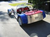
Oh, did I tell you what followed us home from the mountains? There's a photo below. This will be the first "official" use of it for the Locost mission.

I did remove the toolboxes from the side rails of the bed and sell them on Craig's list. That give me enough room in the bed to do all the Locost hauling tasks.
Attachment:
Passenger-3Qtr.JPG
Cheers,