I thought it was time I started a log of my build......
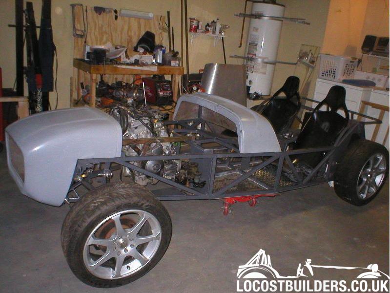
I started with a CMC frame, and am using a Toyota Celica rear axle, miata front spindles.
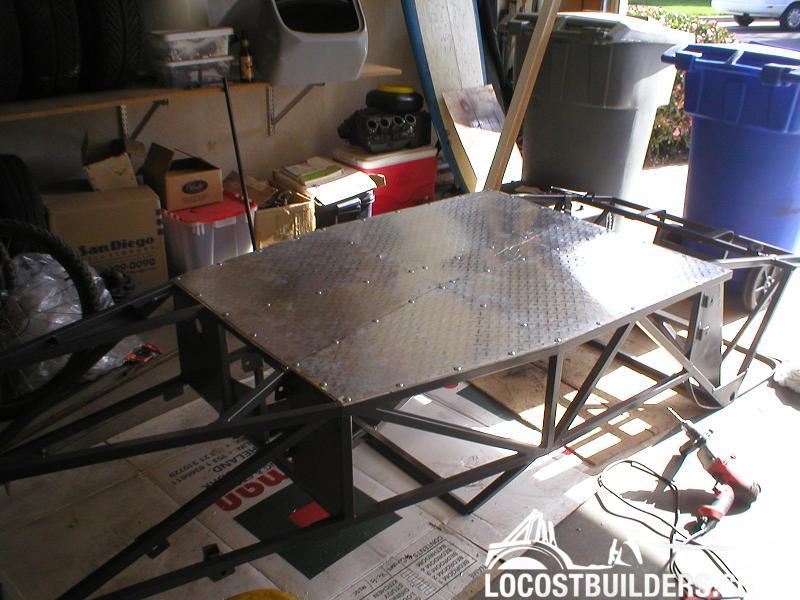
I used 3M VHB adhesive tape for the aluminum floor - a permanent tape used in various applications. Pretty strong stuff.....
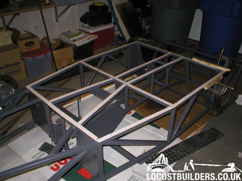
Even though the floor totally held my weight with just tape alone, I chickened out and added a few rivets just for good measure
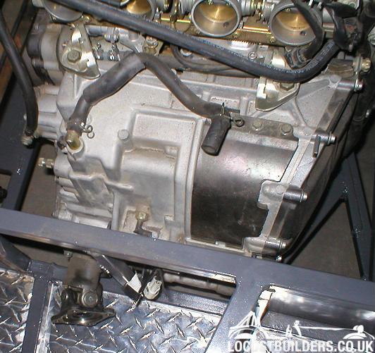
The engine I am using is a Yamaha FJR1300, a sports tourer bike engine, with 150HP and 99ft/lbs torque. It is closely related to the R1 engine
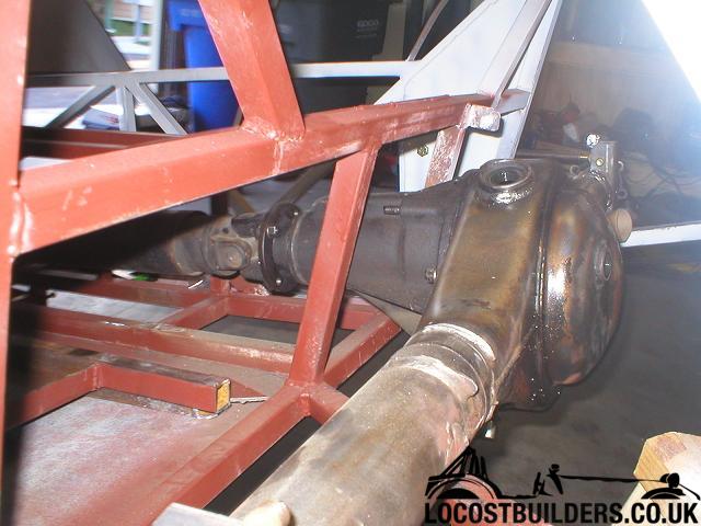
The engine is a shaft-drive, which has pro's and con's. It is already setup for a driveshaft, but unfortunately spins the wrong way.
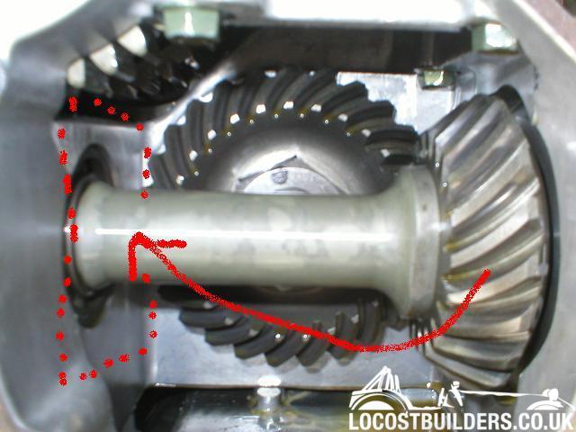
To cure the direction problem, I am mounting the rear axle upside down. This is an earlier mockup
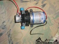
Looking inside the 3rd member, it looks like there will be oiling problems at the pinion bearing, so I am going to use this small electric pump
to pump oil around in a circle, keeping the pinion lubricated. I hope it will work
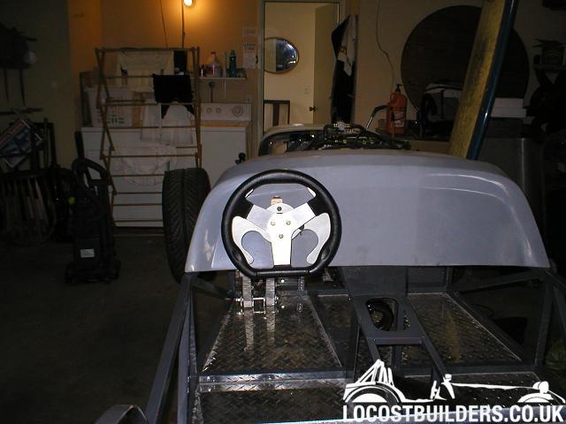
I built a paddle shifter which seems to work nicely, although time will tell when it comes to actually driving it
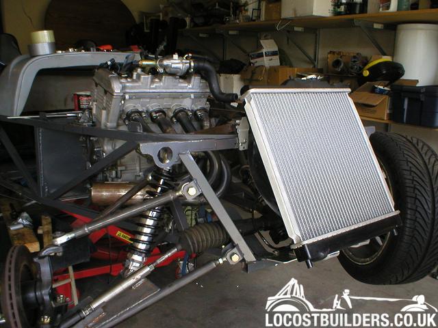
I found an aluminum radiator on ebay which really weighs about nothing...
It is from a Civic. It is a tight squeeze under the nosecone, but fits OK

Coming from Ireland, I travel home from time to time. I was able to bring back a set of aluminum Protech shocks, and a pair of Triton fibreglass seats wwith me on the plane. (Wrapped up the seats and told them they were a baby's car seat!)
I struggled with my headers a couple of weeks ago, but finally got them finished. They didn't work out exactly equal length, but good enough for me....
I have also been working on a solid model in work when I haven't been busy. I was able to beg, borrow and steal some components to save time, but has taken so many hours - I should have put them into the car instead!! I might be finished already
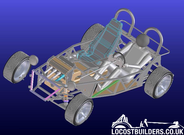
I need to clock up more hours in the garage though, to get it finished. Since starting, I got a ride in a Hayabusa engined westfield, and a Hayabusa engined MK Indy, both local here in San Diego. What a rush! It's little things like this that really give you motivation!
Rob