LocostUSA.com

Learning how to build Lotus Seven replicas...together!
It is currently May 4, 2024, 6:26 am

All times are UTC - 5 hours [ DST ]


Post new topic Reply to topic  [ 113 posts ]  Go to page 1, 2, 3, 4, 5 ... 8  Next
Author Message
PostPosted: April 11, 2013, 10:48 pm 
Offline
User avatar

Joined: January 2, 2012, 6:36 am
Posts: 92
Location: Colorado Springs
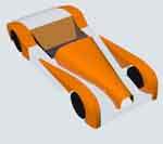
My name is Matt, and I have been reading about locost builds for a few years now. This forum has been exteremely helpful. Life has finally stabilize to the point that I can start on my own. I have decided to name the car the "Parabola V1". I figure if it were to have a name, the better the chance of completeing it! :mrgreen:

It will be building a mid-engine, using a VW 2.2l 16vT. I originally build the motor for a VW that I have a few years ago, but due to some major life changes, all but the built motor and trans were lost during the transitions...

The plan is a scratch built frame, which I am still in final planning stage. I will build a table in this coming week, and hope to pick up the tubing as well. I have a set of Audi hubs and a set of Porsche 996/911 Brembo calipers. I am still waiting on a set of the proper rotors, so that I can begin on the front uprights. This build may not fit the exact definition of "locost", but will be in the same family. :cheers:

I have a couple questions about the frame and the front uprights details.

I will start with the uprights...

I am going to be modeling the geometry off of the Lotus Elise. Of course they will be fabricated to suit my specific needs, but the scrub, castor, and trail will be used. My question is, is there a typical upright height range I should be shooting for, or should the height be choosen according to my wheel diameter and lca pick up height? Also, when setting the KPI up to hit the Lotus' scrub radius of +10mm +-.5, does the actual degree of inclination matter so much? The Elise uses very narrow wheel, and I will be using fairly wide wheels, 9" et35, to be exact. I know I can set it up so the the scrub radius is the same, but the KPI itself will be majorly different. Will this turn out to be any sort of issue? The upright will be designed to allow me to adjust the KPI by using a specific spacer/shim. This will allow for any necessary changes if I were to use different wheels in the future.

On to the frame...

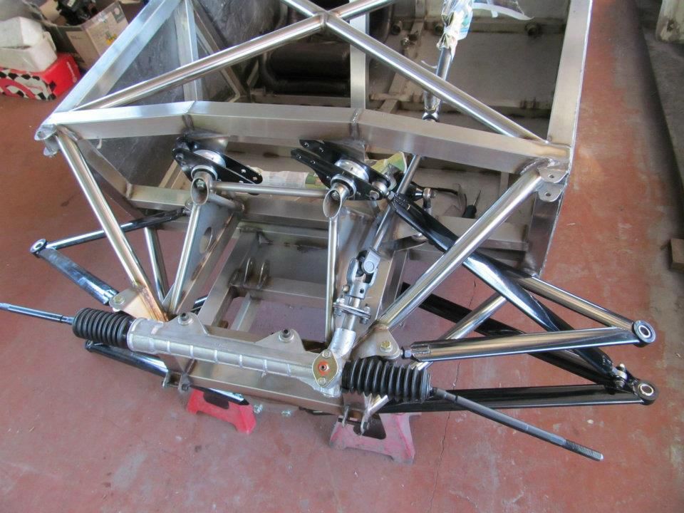
I really like the frame design of the Donto P1. The problem is that it is stainless.

Image

I will be using mild steel. I am wondering if I bump up to a 1.5" square tube, I can get away with the same design, or will I need to add a ton more triangulation, which would basically negate the need for the larger tubing in place of 1"? I would like to stay as far away from the 1500lb. range as possible. I know I will most likely be pushing that weight, but would rather not go over it. Would it just be best to stick with 1" and add to the design, or start from scratch with my own plan?

I am wanting a 95-98" wheelbase, with a 71" front track and 69" rear track.

Begining project pictures to come soon! :thmbsup:

_________________
.:46and2:.


Buy Nutek Forged wheels!


Top
 Profile  
Reply with quote  
PostPosted: April 11, 2013, 11:34 pm 
Offline
User avatar

Joined: July 29, 2006, 9:10 pm
Posts: 3164
Location: Oregon, usually
Fortysixand2 wrote:
...or will I need to add a ton more triangulation, which would basically negate the need for the larger tubing in place of 1"?
I don't think it needs a ton of triangulation, but I'll bet you could double the torsional rigidity with four tubes triangulating the four large trapezoids on the sides (the two L and R on the sides of the engine bay, and the two L and R on the sides of the cockpit). It's time to break out the soda straws and hot melt glue gun.

_________________
Locost builder and adventurer, and founder (but no longer owner) of Kinetic Vehicles


Top
 Profile  
Reply with quote  
PostPosted: April 11, 2013, 11:39 pm 
Offline
User avatar

Joined: April 12, 2010, 5:40 pm
Posts: 2081
Location: san francisco bay area
Well........

I'd suggest PM'ing KB58. You could follow his book and just change to drive train mounts a little bit.
Have you looked thru his Midlana build yet? http://locostusa.com/forums/viewtopic.php?f=36&t=3740&hilit=midlana

_________________
"There are times when a broken tool is better than a sound one, or a twisted personality more useful than a whole one.
For instance, a whole beer bottle isn't half the weapon that half a beer bottle is ..." Randall Garrett


Top
 Profile  
Reply with quote  
PostPosted: April 12, 2013, 12:13 am 
Offline
User avatar

Joined: January 2, 2012, 6:36 am
Posts: 92
Location: Colorado Springs
JackMcCornack wrote:
Fortysixand2 wrote:
...or will I need to add a ton more triangulation, which would basically negate the need for the larger tubing in place of 1"?
I don't think it needs a ton of triangulation, but I'll bet you could double the torsional rigidity with four tubes triangulating the four large trapezoids on the sides (the two L and R on the sides of the engine bay, and the two L and R on the sides of the cockpit). It's time to break out the soda straws and hot melt glue gun.


I tried building a mini frame out of balsa sticks, but I couldn't get it glued well enough. Hot glue just made more of a mess than it was worth for me.

Image

I was somewhat expection to need to add something like the red and blue lines in these pictures. Is this the idea you had as well? If I were to stick with either of these two designs, would it be wise to drop the tubing size down to 1"?

_________________
.:46and2:.


Buy Nutek Forged wheels!


Top
 Profile  
Reply with quote  
PostPosted: April 12, 2013, 12:18 am 
Offline
User avatar

Joined: January 2, 2012, 6:36 am
Posts: 92
Location: Colorado Springs
oldejack wrote:
Well........

I'd suggest PM'ing KB58. You could follow his book and just change to drive train mounts a little bit.
Have you looked thru his Midlana build yet? http://locostusa.com/forums/viewtopic.php?f=36&t=3740&hilit=midlana


I will search around for his build and info about his book. Thanks. I have looked at the Midlana. While I like the design of the car, it isn't quite the style I am looking for. I will be building my own body for the car, and the frame with dictate a good portion of my design. I have a few sketches of what I have in mind, but nothing solid enough to post pictures of yet. I will get that together as soon as I finalize the chassis shape.

_________________
.:46and2:.


Buy Nutek Forged wheels!


Top
 Profile  
Reply with quote  
PostPosted: April 12, 2013, 12:37 am 
Offline
User avatar

Joined: January 2, 2012, 6:36 am
Posts: 92
Location: Colorado Springs
I just bought the Kimini book. After looking over the content of it, it seems like it will be a good read. I typically do extensive google searching before diving into a project, so as of now I am completely confident I can manage this project well. I just think having a good book will help me out even more. Thanks for the suggestion. :cheers:

_________________
.:46and2:.


Buy Nutek Forged wheels!


Top
 Profile  
Reply with quote  
PostPosted: April 12, 2013, 9:42 am 
Offline
User avatar

Joined: January 2, 2009, 1:45 pm
Posts: 1322
Location: Halifax, Nova Scotia
Going back to your introductory post, you asked about the need to increase scantlings if you changed from stainless to mild steel. The short answer is 'no'. A frame design like this is typically more stiffness than ultimate strength driven, although ultimate strength is important too. Young's modulus for structural (mild) steel is similar (if not slightly better) than that for stainless, so a mild steel frame could be stiffer, all else being equal. Of course, you wouldn't have to paint the stainless one, but that's about the only advantage I can see, apart from bragging rights.

Stainless is also a material prone to crevice corrosion. I have some unhappy experience with low-cycle fatigue-related failures of a stainless weldment that attaches the runner plank to the fuselage of my iceboat. Doesn't make me want to be first in line for welded stainless steel suspension brackets on a car .... In fairness to the iceboat case, the commonly used weldment is a pretty dumb design, and should probably be considered a consumable part, but I've often thought that mild steel would be a better material for that application - not as shiny, but probably more fatigue-resistant.

_________________
Warren
Isuzu Pickup/SR20DE, +401 COLD frame
Build Log: viewtopic.php?f=35&t=11601


Top
 Profile  
Reply with quote  
PostPosted: April 12, 2013, 11:57 am 
Offline
Mid-Engined Maniac

Joined: April 23, 2006, 8:26 pm
Posts: 6421
Location: SoCal
I've seen stainless rust right along weld lines. While there's probably stainless steel alloys which don't do this, the cost has to be factored in to whether it's really saving any money. Plus, I don't want anything shiny (like polished stainless) in the passenger compartment that reflects sunlight into my eyes.

_________________
Midlana book: Build this mid-engine Locost!, http://midlana.com/stuff/book/
Kimini book: Designing mid-engine cars using FWD drivetrains
Both available from https://www.lulu.com/


Top
 Profile  
Reply with quote  
PostPosted: April 12, 2013, 6:22 pm 
Offline
Automotive Encyclopedia
User avatar

Joined: December 22, 2006, 2:05 pm
Posts: 8048
If you want to use a frame that looks like this to hang sheetmetal or run bare bones, great, but the tubes are not the right place in the front or the rear. None of the nodes appear to align with any suspension attachment points. The frame would be significantly heavier just adding extra tubes where the suspension goes, and there seems to be no distinction in size between primary and secondary structure, just styling.


Top
 Profile  
Reply with quote  
PostPosted: April 13, 2013, 1:05 am 
Offline
User avatar

Joined: January 2, 2012, 6:36 am
Posts: 92
Location: Colorado Springs
Thanks for the info about mild steel vs. stainless. I have never had a desire to deal with building a stainless frame, so I hadn't read much about it, just assumed it was superior for strength. I'm sure that is a common misconception.

I agree the rear portion of the frame is poorly designed. I would not follow that aspect of it for a handful of reasons.

The front isn't design for the traditional pick up points. The assembled suspension makes more sense of it.

Image

Image

The lower arms at extremely long! I'm not quite sure what the true need for the length is. The chassis has been FIA approved. I figure that is agood start to choosing a design to model after. The designer's name is Hector Tito Perez. I personally don't know much about his chassis', but google says, "he is a renowned Argentinian chassis designer, with over 400 designs to his name."

I'm not sure what that bit of info is truly worth, but I see it as he has to know a good bit more than I do, and just may be worth following his lead. I am interested in the opinions of areas that could use improvement. I am trying to solidify the plan within the next week and a half.


Is it necessary to have a distinct primary and secondary tubes? I guess I have been assuming using all 1.5" square would just provide extra rigidity. I have zero issue with dropping down to 1" in certain places. The more weight I can cut, without sacrificing strength and rigidity the better.

I am a painter, so auto body is a passion of mine, as well as fabrication. I have a decent amount of experience with composites, and plan to build some sort of a body for the car. It will not be a full body, but will have a decent about of shape to it. I am trying to keep this in mind while figuring the chassis design.

_________________
.:46and2:.


Buy Nutek Forged wheels!


Top
 Profile  
Reply with quote  
PostPosted: April 13, 2013, 3:40 am 
Offline
User avatar

Joined: July 29, 2006, 9:10 pm
Posts: 3164
Location: Oregon, usually
Fortysixand2 wrote:
I was somewhat expection to need to add something like the red and blue lines in these pictures. Is this the idea you had as well?
Yep, that was the idea, I was thinking the red lines in your top drawing, and the blue lines in both--you could eliminate the blue ones if you weld in a firewall behind the seats and use it as a shear web.
Fortysixand2 wrote:
I were to stick with either of these two designs, would it be wise to drop the tubing size down to 1"?
I sure think you could, but all else being the same, bigger tubes = stiffer chassis. Also bigger tubes = heavier chassis, so you have to decide how much you're willing to trade weight for stiffness.

_________________
Locost builder and adventurer, and founder (but no longer owner) of Kinetic Vehicles


Top
 Profile  
Reply with quote  
PostPosted: April 13, 2013, 6:36 am 
Offline
Toyotaphobe
User avatar

Joined: April 5, 2008, 2:25 am
Posts: 4829
Location: Fort Worth, Texas
How is the back end of the bottom front wishbones connected? Another br@cket like we can see in the front or is there a tube there to anchor it more soundly?

_________________
mobilito ergo sum
I drive therefore I am

I can explain it to you,
but I can't understand it for you.


Top
 Profile  
Reply with quote  
PostPosted: April 13, 2013, 7:03 am 
Offline
Automotive Encyclopedia
User avatar

Joined: December 22, 2006, 2:05 pm
Posts: 8048
Without any tabs, it appeared the suspension was short armed and would hang on either side of the footwell.

You say you want to bump up to 1.5" tube and use steel, but it appears the tubes are at least that big.

The untriangulated box for the front suspension gets away with it by using such large deep crossection / buttress tubes.
One could use smaller tubes of thicker wall and add diagonals, but then the weight would probably be nearly as much.

I'm sure the stainless used is much thinner wall than what we normally use. To replicate this at a reasonable cost would require tubing in diameters and walls normally found in exhaust tubing, which is stiffer and similar in weight to smaller, thicker walled dom. I'd step up the wall around the cage for protection.

For such thin walls, attachment points cannot just be but welded, because they can tear out of the thin metal. Lots of welded area, with a load spreader plate / doubler in some cases.

Or, determine what tubing was used, size and wall, then order the same in steel and replicate. Weight and strength should be close if not the same, without the issues that have been mentioned. This is more in keeping with your time table. I doubt it will be over 500 lbs, even with additional diagonals and a little more wall thickness.


Top
 Profile  
Reply with quote  
PostPosted: April 13, 2013, 9:37 am 
Offline
User avatar

Joined: November 12, 2008, 6:29 am
Posts: 3567
Fortysixand2 wrote:

The front isn't design


Add an "..ed" to the end there and you got it 100%.

It's more of a case of spotting what's right with that entire design from front to rear rather than what's wrong with it.


Top
 Profile  
Reply with quote  
PostPosted: April 13, 2013, 10:27 am 
Offline
The voice of reason
User avatar

Joined: January 10, 2008, 4:47 pm
Posts: 7652
Location: Massachusetts
Quote:
I am trying to solidify the plan within the next week and a half.


Enthusiasm is great and you'll need plenty of that to finish your project. :cheers:

I would recommend some caution and stepping back a bit though. I see lots of issues with copying someone's frame without much information on what they are trying to do, how they are doing it and what they are using. "FIA approved" is rather an open statement or could be. I wouldn't take it as an indication that it is safe or what you build from pictures will be safe.

There are lots of things you can do upfront to help yourself get this right. You can do the frame and analyze it in software modeling. If you prefer not to do something like that and work in the real world - $100 of wood stock and a table saw will build you a full size frame to study. Then you can literally build the entire car including body and then do the frame last.

If you know what you are doing ( say making a second copy ), people find they can do a frame in a weekend or two. So it isn't really much help to do it upfront, it just makes all your thinking mistakes into reality that you have to live with or redo.

You can take wood 2"x4", cut that stock to 1 1/2" square or whatever and join with plywood gussets and screws. You can clamp this to your table and use a 2x3 lever to try bending or twisting your frame and see where it is week. You can sit in it and see what it looks like from the inside. You can fit the suspension and drivetrain. You can even drive it around your yard.

Then make up a frame and move everything over. People often build their frame and get the car ready to run and then take it apart just to paint the frame, so there is no extra effort in the trial run...

_________________
Marcus Barrow - Car9 an open design community supported sports car for home builders!
SketchUp collection for LocostUSA: "Dream it, Build it, Drive it!"
Car9 Roadster information - models, drawings, resources etc.


Top
 Profile  
Reply with quote  
Display posts from previous:  Sort by  
Post new topic Reply to topic  [ 113 posts ]  Go to page 1, 2, 3, 4, 5 ... 8  Next

All times are UTC - 5 hours [ DST ]


Who is online

Users browsing this forum: No registered users and 25 guests


You cannot post new topics in this forum
You cannot reply to topics in this forum
You cannot edit your posts in this forum
You cannot delete your posts in this forum
You cannot post attachments in this forum

Jump to:  
POWERED_BY