LocostUSA.com

Learning how to build Lotus Seven replicas...together!
It is currently April 19, 2024, 5:56 pm

All times are UTC - 5 hours [ DST ]


Post new topic Reply to topic  [ 373 posts ]  Go to page Previous  1, 2, 3, 4, 5 ... 25  Next
Author Message
PostPosted: September 9, 2014, 11:57 pm 
Offline
User avatar

Joined: August 18, 2014, 11:20 pm
Posts: 185
Location: San Antonio, Texas
The upper and lower frame tubes are cut, as is the front end assembly. It took a bit of thought to cut members LA and LB:

Attachment:
Front members.jpg


I guess the sevenesque website wasn't kidding when indicating this is perhaps the trickiest part of the Book chassis to get straight. :-|
My cuts and angles are correct, however my fixturing will need some work. Once I had LA, LB, LC, LD in place I tacked them together. But ensuring the parallelism of LD and LC is a bit of an art. I'll need to grind down my tacs and develop a solid jig which maintains the 3" offset and LA/LB angles.


I'm finding that I can really only work on the car 2~3 hours max per day after work. Which is really a nice change after staring at spreadsheets and preparing for meetings all day.


You do not have the required permissions to view the files attached to this post.

_________________
There is no such thing as mechanical failure, only a lack of attention to detail.


Top
 Profile  
Reply with quote  
PostPosted: September 10, 2014, 11:39 pm 
Offline
User avatar

Joined: August 18, 2014, 11:20 pm
Posts: 185
Location: San Antonio, Texas
Holy smokes! I absolutely love auto darkening welding helmets! It's so much easier to get setup to weld with this. It was like kissing a girl for the first time.
Attachment:
Welding helmet.jpg


Well the bottom rail took longer than expected. The most time consuming part is checking angles, placements, tube fitment and evenness.
Attachment:
bottom rail tacked.jpg


I was adamant the front end assembly tubes must absolutely be straight.
Attachment:
front end assembly fixtureing.jpg

Attachment:
front end assembly fixtureing side view.jpg

Attachment:
front end assembly fixtureing top view.jpg


I spent probably a good part of two hours ensuring these tubes were situated as per book chassis drawings. I'll tack the front end together tomorrow, and then move onto the upper rail. I've started making little 45 degree taco gussets to reduce the stress concentration of where the A-arms will meet the chassis. I intend to triangulate the longitudinal member attached to the uprights.


You do not have the required permissions to view the files attached to this post.

_________________
There is no such thing as mechanical failure, only a lack of attention to detail.


Top
 Profile  
Reply with quote  
PostPosted: September 11, 2014, 12:26 am 
Offline
Toyotaphobe
User avatar

Joined: April 5, 2008, 2:25 am
Posts: 4829
Location: Fort Worth, Texas
Let me know how you like the Kobalt helmet after you use it a while. I need a new helmet and have considered that one, but after all the talk about burning your eyes from helmets that don't react quickly and seeing battery issues I've been afraid to pull the trigger on one.

_________________
mobilito ergo sum
I drive therefore I am

I can explain it to you,
but I can't understand it for you.


Top
 Profile  
Reply with quote  
PostPosted: September 11, 2014, 11:29 pm 
Offline
User avatar

Joined: August 18, 2014, 11:20 pm
Posts: 185
Location: San Antonio, Texas
carguy123, I've been fiddling with the adjustments on the helmet and it darkens very fast. Lens auto-darkens in 1/20,000th of a second according to the website. I can tune the darkness which most certainly helps me suck less at running a bead.
Attachment:
helmet adjustments.jpg


17 reviews for the helmet, and 4.9/5 stars.
http://www.lowes.com/ProductDisplay?par ... RWidgetID/

(Granted, this is a Lowes website, so it's likely edited and thus biased.)

The front end assembly, and uprights are tacked and in place.
Attachment:
top rail and bottom rail.jpg


I flipped the chassis upside down and to check fitment and upon mocking up the top rail, the tube notches definitely do not line up on ALL of the upper rail tubes. Now, I really don't want to insinuate the book chassis is incorrect, but I'm fairly certain the miter angles for the entire upper rail are incorrect in the pdf. Or it could simply be the nut behind the miter saw. :wink:
Attachment:
incorrect notches.jpg


Not too big of a deal. I'll have to remake six tubes and check and recheck fitment as I go. I can still use these tubes for triangulation and my small 45 degree taco gussets. Note the self: do not preemptively cut tubes assuming it will save time.


You do not have the required permissions to view the files attached to this post.

_________________
There is no such thing as mechanical failure, only a lack of attention to detail.


Top
 Profile  
Reply with quote  
PostPosted: September 12, 2014, 8:26 am 
Offline
User avatar

Joined: September 22, 2005, 8:12 am
Posts: 1880
Location: 4AGE in S.E. Michigan
I would just dress the tube angle to get the correct weld gap. As long as both sides are at the same angle and are symmetrical, it really will not be an issue. You only need to place the control arm brackets in the right location, i.e. hole locations. Dave W


Top
 Profile  
Reply with quote  
PostPosted: September 12, 2014, 9:29 am 
Offline
The voice of reason
User avatar

Joined: January 10, 2008, 4:47 pm
Posts: 7652
Location: Massachusetts
Quote:
I need a new helmet and have considered that one, but after all the talk about burning your eyes from helmets that don't react quickly and seeing battery issues I've been afraid to pull the trigger on one.


They offer double protection, that's why you see such a green tint thru them. Even if they fail to darken, they block sufficient UV and IR (red and blue) light to be safe. The number was printed in my manual but I forget, something like 14.

Your eyes might get tired from the bright flash, but it is not the colors that will really harm you. I think fast ones are cheap now.

_________________
Marcus Barrow - Car9 an open design community supported sports car for home builders!
SketchUp collection for LocostUSA: "Dream it, Build it, Drive it!"
Car9 Roadster information - models, drawings, resources etc.


Top
 Profile  
Reply with quote  
PostPosted: September 12, 2014, 1:56 pm 
Offline

Joined: August 11, 2012, 4:44 pm
Posts: 1422
Location: Charlotte, NC
Looking forward to seeing how this one turns out. Good luck with your build.

_________________
30 years old, not sure what I want to be when I grow up…


Top
 Profile  
Reply with quote  
PostPosted: September 12, 2014, 2:03 pm 
Offline

Joined: August 11, 2012, 4:44 pm
Posts: 1422
Location: Charlotte, NC
horizenjob wrote:
Quote:
I need a new helmet and have considered that one, but after all the talk about burning your eyes from helmets that don't react quickly and seeing battery issues I've been afraid to pull the trigger on one.


They offer double protection, that's why you see such a green tint thru them. Even if they fail to darken, they block sufficient UV and IR (red and blue) light to be safe. The number was printed in my manual but I forget, something like 14.

Your eyes might get tired from the bright flash, but it is not the colors that will really harm you. I think fast ones are cheap now.


Dont buy the northern tool one. It sucks. I cant see much out of it and the helmet itself is cheaply made. Ive had 2 both of the head straps have broke. After wearing a nice auto helmet Im going to save up and buy a really nice one, talking like a $300 helmet.

_________________
30 years old, not sure what I want to be when I grow up…


Top
 Profile  
Reply with quote  
PostPosted: September 13, 2014, 1:10 am 
Offline
User avatar

Joined: August 18, 2014, 11:20 pm
Posts: 185
Location: San Antonio, Texas
Gents,

The majority of the chassis tubes are in place and tacked together:
Attachment:
chassis at 80 percent.jpg


I have about 20~30 hours into the chassis thus far.

Checking for parallel placement of horizontal members from the rear:
Attachment:
rearview firewall.jpg


(Sorry, I had to break out the laser...I couldn't resist.)

Front view:
Attachment:
front view.jpg


The last time I was around a "scale" version of the Lotus 7 replica was riding shotgun in a Brunton SuperStalker with a supercharged GM V6 at Virginia International Raceway. I recall it was a very small car.
BUT GOOD LORD THIS IS GOING TO BE A TINY AND VERY NARROW CAR. I think this has now hit me in terms of how small this thing really is.

Given the fact that I'll be driving this around Texas, and perhaps back and forth to the office on occasion, I'm fairly sure this car will look VERY out of place amongst the usual F150's, Rams, Excursions, and H3's in Texas traffic.

Nevertheless, I am very excited about making more progress on the car. Today I tried to pick up 1.5" OD, 0.035" wall 4130 round tubing, and bend a new lightweight main rollhoop to copy the Caterham R500, but the local metal shop only had a very rusted 10ft stick. =-(

I'm rethinking using the integra roll bar, since that weighs 68 lbs. Given how light the Book Chassis is, it would be a sin to make it needlessly heavy.

Overall, I am thoroughly enjoying this build. I'm itching to drive it already, and flog it at the local Texas Spokes/SASCA autocross. It has been a while since I've turned a wheel in anger...charge up the GoPro, I think it's well overdue.
:zoom:


You do not have the required permissions to view the files attached to this post.

_________________
There is no such thing as mechanical failure, only a lack of attention to detail.


Top
 Profile  
Reply with quote  
PostPosted: September 13, 2014, 1:22 am 
Offline
Mid-Engined Maniac

Joined: April 23, 2006, 8:26 pm
Posts: 6420
Location: SoCal
LateralScience wrote:
... Today I tried to pick up 1.5" OD, 0.035" wall 4130 round tubing, and bend a new lightweight main roll hoop to copy the Caterham R500...

I hope this isn't literally what you meant. If it is, and the car ever goes upside down, you'll lose your head. I believe that the minimum DOM tubing thickness for a roll hoop is 0.085". Find a copy of the SCCA or NASA rulebook and confirm.

_________________
Midlana book: Build this mid-engine Locost!, http://midlana.com/stuff/book/
Kimini book: Designing mid-engine cars using FWD drivetrains
Both available from https://www.lulu.com/


Top
 Profile  
Reply with quote  
PostPosted: September 13, 2014, 9:09 am 
Offline
User avatar

Joined: August 18, 2014, 11:20 pm
Posts: 185
Location: San Antonio, Texas
Crap. You are correct Kurt. GCR states min of 0.095" wall for 1.5" tubing.
I could go .080" with 1.375" in 4130.

Indeed the 1.75" OD 0.128" wall is most certainly overkill for our cars. But this would give me piece of mind.

_________________
There is no such thing as mechanical failure, only a lack of attention to detail.


Top
 Profile  
Reply with quote  
PostPosted: September 13, 2014, 9:52 am 
Offline

Joined: September 19, 2009, 12:33 pm
Posts: 498
LateralScience wrote:
Also, does anyone have suggestions on building a cost effective tube bender and chassis rotisserie?

Thanks!
-Andrew


Whether you go with the JD2, Pro Tools, or JMR bender, it's about $300 just to get the bender. Comparison thread here. And dies for 1.75-2" material will run $270+ for each size, so expect to pay about $600 to hand-bend a single diameter of tubing.

If you're planning to adapt it to air/hydraulic, I'd go with the Got Trikes kit from the start. I bought the Pro Tools bender and with what I spent building a stand and adapting the Harbor Freight air over hydraulic cylinder, it would have been cheaper just to get the Got Trikes kit.

_________________
Ford 5.0 into an M3
mikaelvroom.com | @MikaelVroom


Top
 Profile  
Reply with quote  
PostPosted: September 14, 2014, 12:57 am 
Offline
User avatar

Joined: August 18, 2014, 11:20 pm
Posts: 185
Location: San Antonio, Texas
I stayed late after hours and used the bender in our machine shop with discretion.

Main Roll hoop: 1.75" OD, 0.135" wall. (I was mistaken about the 0.128" wall I mentioned in a previous post.)
Attachment:
Main roll hoop 1.75 dia 0.135 wall.jpg


God this thing is heavy. The width of the main roll hoop is 41" CTC, which puts it inline with the standard Locost7 book chassis width.
Attachment:
main roll hoop front view.jpg


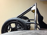
Note the harness bar is at the same height as the rear uppermost member (Book chassis member "O" I think), to meet K3 and K4 members. The bottom of the triangulation members (meeting the main roll hoop and harness bar) ties into the rear lower control arm inboard point of the radius rod.

I indicated earlier that it has been many moons since my welding class. I wasn't kidding:
Attachment:
Sorry no showcar welds here.jpg


Not exactly "stacked dimes" but more like stacked bird ****.

Nevertheless, I think it'll hold. Checking it against the chassis:
Attachment:
checking rollhoop against chassis.jpg


The bottom of the main roll hoop leaves barely an inch of clearance above my helmet. Without a helmet I've got plenty of clearance.
Attachment:
Main roll hoop and helmet.jpg


This is cutting it close, but I think I'll just go with it.

With regards to the front suspension, I've ordered a set of 1999-2005 Miata front spindles from ebay, and I'll need to fabricate front LCA once they arrive. for the UCA, I'll just follow suit for standard Locost7:
http://www.speedwaymotors.com/Adjustabl ... 2095.html/

I've been giving the rear suspension some thought. Here is where I will cut the upright:
Attachment:
location of cutting the upright.jpg

Essentially the cross section is an I-beam, and the web 0.825" thick.
Considering I will be loading a 1/2" diameter grade 8 bolt in double shear. Assuming a grade 8 bolt yield strength of 130ksi, and an allowable load of 1000lbf (est.), this gives an allowable stress of 2.55 ksi, which results in a Factor of Safety against yield of 52.

One could argue the smallest cross section of the upright above the bolt would have the highest stress, and I should consider the yield strength of the cast iron instead, but that material section above the bolt is does not experience bending moments as the material under the bolt (between the UCA bolt and spindle). Granted there is likely bearing stress from half of the cylindrical surface of the bolt acting on the upright, but I'm fairly sure the material above the bolt would not come close to the Von Mises stress.

Also, if we look at the OEM upper control arm pickup point, the cross section where the ball joint tapered shaft enters the upright is substantially smaller than the section I will be using. I do not intend on welding onto the cast iron upright, as this would likely reduce its' yield and tensile strength and likely fracture at the heat affected zone.

I intend on using 5/8"-18 heim joints with AFCO steel swaged suspension tubes for adjustable camber. Likewise, the same member for toe links.
http://www.speedwaymotors.com/AFCO-1954 ... 0947.html/

In terms of ride height of the car, I'd like to stay low at around 3" to 4". The problem is if the car is this low with 16" wheels, the angle of CV axles increases, and there is likely an efficiency loss. Ideally, I would love to rotate the engine 90 degrees forward to lower the CG of the engine, and raise the inboard axle point, and then run a dry sump. This would lower the CG of the car, as well as allow for more horizontal axle positioning. But, I'm only dreaming, as a dry sump would not be cheap.

Anyhow, I'm also thinking of going with 13x10" wheels for solo II:
http://www.bassettwheel.com/legends_mini.html/
And some used 13x9.5" used hoosiers:
http://www.ebay.com/itm/679-2-USDRRT-Ho ... 601721234/

This would help aid in lowering the car. However, there is an issue with the willwood 12.2" rotors not clearing.

I also need to start thinking about steering rack placement, and if I want to use the integra steering rack with a Coleman 2:1 steering quickener.

And then there is the rest of the car:
Steering column support
Pedal Box mount
Shifter linkage and support
the list goes on...

Also, I'd like to place the radiator, fuel tank, and battery infront, and all in a line and longitudinally (in place of where the engine would have been). I was thkinking of picking up four bathroom scales and corner weight the car before I start fabricating support beams and tabs. The car will likely be biased towards the rear left, as both the engine and driver are both on the left.

Anyhow, it's late, and I've run out of shielding gas. This is like taking small bites out of an elephant one nibble at a time.


You do not have the required permissions to view the files attached to this post.

_________________
There is no such thing as mechanical failure, only a lack of attention to detail.


Top
 Profile  
Reply with quote  
PostPosted: September 14, 2014, 11:14 am 
Offline
The voice of reason
User avatar

Joined: January 10, 2008, 4:47 pm
Posts: 7652
Location: Massachusetts
I think we are a long way from a Midlana here, so Kurt would probably appreciate it if you change the thread title. You can do that by editing the subject line in your first post. Looks like you're having fun and elephant never tested so good. :)

_________________
Marcus Barrow - Car9 an open design community supported sports car for home builders!
SketchUp collection for LocostUSA: "Dream it, Build it, Drive it!"
Car9 Roadster information - models, drawings, resources etc.


Top
 Profile  
Reply with quote  
PostPosted: September 14, 2014, 1:45 pm 
Offline
User avatar

Joined: August 18, 2014, 11:20 pm
Posts: 185
Location: San Antonio, Texas
I suppose you are correct. My apologize Kurt.

I guess this is more of a simple standard book chassis build, just with a transverse FWD engine pushing it.

_________________
There is no such thing as mechanical failure, only a lack of attention to detail.


Top
 Profile  
Reply with quote  
Display posts from previous:  Sort by  
Post new topic Reply to topic  [ 373 posts ]  Go to page Previous  1, 2, 3, 4, 5 ... 25  Next

All times are UTC - 5 hours [ DST ]


Who is online

Users browsing this forum: No registered users and 13 guests


You cannot post new topics in this forum
You cannot reply to topics in this forum
You cannot edit your posts in this forum
You cannot delete your posts in this forum
You cannot post attachments in this forum

Jump to:  
POWERED_BY