A few updates, but not a lot to show for all of the work I've put in over the last few weeks.
First, I bought the 13 inch drill press from Harbor Freight. It cost just over $200, and it's pretty good for that price. They are making new versions of the larger presses, and they are better than the old ones. Casting, chuck, fit and finish, motor; everything's just better. I also picked up a real chop saw while I was there. Finally. I wish I had bought both of these a year ago.
Attachment:
IMG_2696.jpg
Attachment:
IMG_2697.jpg
First thing I did with the new drill press is start drilling 1" holes in 11 gauge steel. It does just fine if you go slowly. This part is the first piece for my front upper control arm mount setup. I changed directions on this, as I wanted something cleaner and simpler. I had do drill a bunch of holes though. The square tube is 1.75" x 11 gauge. Heavy stuff, but it's going to do some important jobs and I'm not using that much of it.
Attachment:
IMG_2698.jpg
I then beveled the holes pretty significantly and welded in 11 gauge compression tubes. Everything was ground flush and I hit it with a flap disk to clean up. Then I did the same thing with a smaller square tube that I welded on right in the middle, at 90 degrees. Both the longer and shorter tubes got end plates welded on. Finished and mounted, but without any of the connecting round tube bits, they look like this:
Attachment:
IMG_2727.jpg
The centers of the holes will give me the C5 Corvette factory geometry, only with an extra 3/8" room for additional negative camber. So I can either adjust the alignment with the eccentric bolts on the lower control arms, as normal, or use shims on the upper control arms. However, you can see that I also have one hole in the top of the UCA mount tube between each pair of holes in front. This allows for greater adjustability. I can simply bolt a 5" piece of 2" angle to the square tube and weld connection points for whatever UCA geometry I'd like to try. So I can change roll center height (has very little effect on roll center fixity with this setup), change anti-dive amounts, go a little crazy with caster, or whatever. I toyed with making the basic through-the-bolt-holes setup have a little less anti-dive, as I've seen that most race car custom setups with the C5 parts look like they run very little, but in the end I decided the factory location was a better default.
The square tube on the top is the shock mount tube. You can see the two holes in the front, but there's also a transverse hole that is exactly between. This is essentially the place where I'll bolt on the shock mount bracket. Again, I can make the bracket-to-tube interface a simple piece of 2" angle, or I can make it more complicated. I decided to go with a bolt-on bracket because I don't know what shocks I'm going to run. I already have the Corvette transverse springs and factory shocks, so it will be free to run those and I plan to do that in the beginning. However, I suspect I'll eventually want to go to coilovers, and a mount that works for the factory shocks will not support other kinds of units very simply. The obvious solution is a bolt-on bracket. I also like it that it allows me to change the angle of the shocks some, and to use different lengths of shocks. I can run whatever parts I can find for cheap, just have to build a new bracket.
The caps on the ends of the square tubes are the connection points for round tubing that will interface with other parts of the chassis. I decided on this as a reasonable way to get square tubing to work with round. As the square is 1.75" like the round, it interfaces nicely as long as they're on the same plane, but as soon as they're not it's a problem. I really wanted to use square tubing for the shock and control arm mounts because it's stronger/stiffer in the direction of the primary load and it makes a much simpler interface for brackets. But it's heavy and only plays nicely with round in one plane. So i'm using enough square to get the job done, then plating the end and switching to round.
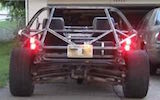
The little pointers in the picture are my fixed points in space that I used to locate the UCA mount holes. First I took the tube chassis off the subframes (no, the chassis is not as heavy as the picture makes it look, this was just a simple solution), which only took about 10 minutes:
Attachment:
IMG_2724.jpg
Then, aligned, bolted down, and measured the mounting points. I measured the height of the bolt holes from the floor (my build table, it's pretty flat), the fore/aft from the front machined surface of the LCA on the subframe, and the width from the LCA bolt in its widest position. I measured both sides and found ways of measuring where I could get consistent numbers, mostly using a pair of squares a level and a few straight edges. I think the tolerances are within 1/16".
Attachment:
IMG_2725.jpg
Then I bolted the chassis back down square on the mounting pads (at least in the front), located the points in space, and fitted the UCA/shock mount assembly accordingly.
Attachment:
IMG_2726.jpg
Finally, I fitted a round tube on the bottom to hit one of the 'hard points'. After tacking on the round tube I removed the assembly, fully welded the round tube, and final fitted each side. I'll have one more look and measure before I tack them in, but I think they're pretty close to dead on.
Attachment:
IMG_2728.jpg
The UCAs won't bolt onto the holes directly, but to hit the factory locations they need to sit 1 3/8" out board, so for now I'll probably just drill holes in some 1.25" square tube and use little pieces of that for spacers. Eventually, if and when I keep the factory geometry, I'll use solid aluminum for the spacers. I'll just need a bar the right size that I can cut and drill.
Hopefully this big update makes up for the last few weeks.
-Graveyard