LocostUSA.com

Learning how to build Lotus Seven replicas...together!
It is currently April 19, 2024, 5:56 am

All times are UTC - 5 hours [ DST ]


Post new topic Reply to topic  [ 42 posts ]  Go to page Previous  1, 2, 3  Next
Author Message
PostPosted: October 3, 2016, 7:56 am 
Offline
User avatar

Joined: December 7, 2012, 8:28 am
Posts: 1410
Location: Sarasota
Great job on the test run. I think moving the front wheels forward to give you a longer wheelbase should help with stability. It should also slightly reduce the road noise due to a longer lever.

_________________
2015 & 2016 EMod Florida State Autocross Champion
2013 & 2014 DSP Florida State Autocross Champion

Scrap Metal Build Log viewtopic.php?f=35&t=14558


Top
 Profile  
Reply with quote  
PostPosted: October 3, 2016, 9:36 am 
Offline
User avatar

Joined: October 19, 2010, 11:57 am
Posts: 507
Location: Waterloo, WI
Nice! :cheers:

_________________
-Keith


Top
 Profile  
Reply with quote  
PostPosted: October 3, 2016, 11:30 am 
Offline
User avatar

Joined: April 26, 2008, 6:06 pm
Posts: 3268
Location: Under the weather. (Seattle)
Congrats on the successful maiden voyage. :cheers:

ckouba wrote:
They do flex liberally under lateral loading but they do not catastrophically fail.
...Yet. I don't know what type of plastic those wheels use, but watch out for fatigue. Some camber might reduce lateral deflection, but would also add some friction as well. Although with solid tires it might not be as bad as pneumatic tires.

_________________
-Justin

"Orville Wright did not have a pilots license." - Gordon MacKenzie


Top
 Profile  
Reply with quote  
PostPosted: October 9, 2016, 7:57 am 
Offline

Joined: March 1, 2008, 8:42 am
Posts: 103
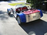
More work done over the past 3-4 days documented with a single, crappy cell phone pic:

Image

Triangulation of the chassis has been done, floor area reinforced (more still to be added), rear bumper added, fender support fabbed, roll structure re-enforced, rear tow point added (not visible), the 6-point harness I found for $30 (so, no, it's not FIA rated, but what a find still!) has been installed, and nose cone skeleton constructed (also not visible). I am running out of things to weld on to the frame and am feeling like it might be time to actually paint it soon, which is pretty exciting. I want to have my pneumatic tires and new 24" wheels in hand and mounted up before I commit to that.

In other news, chassis #2 is starting to take shape. Bill decided it's likely just a little too much work to get the flyer into the shape he'd feel comfortable tackling the course at full speed. He'd rather have a robust chassis with ackerman steering and (most importantly) functional brakes. After much perusing of the internet, it appears the most common wheel size is 20", and we may be inclined to pursue using that size. Based on how the 24" wheels do with my car after adding in some weight, we may change his design brief to accommodate the smaller wheel size. Or not. The good news is, we have started the frame build with the ability to compensate for that (to a point).

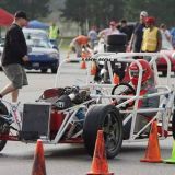
Bill looking like a kid on Christmas morning:
Image

Making vroom, VROOM noises a couple hours later:
Image

It's amazing what having constructed the first chassis has done for my ability to construct the second. It appears to be WAY more square than my first one. There are a couple of design features I've come up with to make things a little easier for construction and tuning down the road, and which we are starting to add into the base build. It will be fun seeing how they pan out in the newest chassis.

Chris


Top
 Profile  
Reply with quote  
PostPosted: October 15, 2016, 4:43 pm 
Offline

Joined: March 1, 2008, 8:42 am
Posts: 103
My hydraulic brake was dragging slightly and I wanted to go cable-activated to release the drag. I also needed a brake for Bill's car... so I found a complete set of front and rear, mechanical disc brakes for $26 new on Amazon.

Yeah, that's right- $26!!:
Image


Brake installed on my car:
Image

Then I came up with a much more ingenious (read: convenient, ergonomic, etc...) mounting point for the brake lever:
Image

Then I hired some new test drivers (neighbor kids) to see if it worked:
Image

At speed:
Image

Image

It was a very successful day! Brake works great and there is ZERO drag when not applying braking force. New wheels and tires should arrive in the next week but have some other projects going on which will push when I can get back to it. I also tried my hand at bodywork. Let's just say I have a LOT of learning to do.

Chris


Top
 Profile  
Reply with quote  
PostPosted: October 15, 2016, 5:34 pm 
Offline
The voice of reason
User avatar

Joined: January 10, 2008, 4:47 pm
Posts: 7652
Location: Massachusetts
I'm really glad to see your crew is so helpful, and that these days kids learn to wear helmuts. I don't know how our generation survived.

I have a small comment on the steering geometry. It looks like you are putting caster into the suspension to give more trail, but also you have put trail into the little blocks that hold the front axles? I don't think you are in trouble here, but the way this is being done is giving you conflicting influences.

If you get one of your testing helpers to hold a good metal rule up against the front of the chassis while you turn the wheel I think you will see that it lowers down when you turn the wheel a good amount. So the weight on the front is encouraging the wheel to move off center. It's the opposite effect as King Pin angle.

Your setup may work fine and you can disregard then, but if it seems a little less stable than you like - it's something to keep in mind.

Fun project. :cheers:

_________________
Marcus Barrow - Car9 an open design community supported sports car for home builders!
SketchUp collection for LocostUSA: "Dream it, Build it, Drive it!"
Car9 Roadster information - models, drawings, resources etc.


Top
 Profile  
Reply with quote  
PostPosted: October 17, 2016, 5:20 am 
Offline

Joined: March 1, 2008, 8:42 am
Posts: 103
Marcus,

Thank you for taking a good close look at what I built. I needed to have some mechanical trail because I couldn't co-locate the wheel mounting bolt with the upright locating bolt. When I made the uprights, I displaced the wheel bolt aft by a bit, thinking the effects would be complementary. You are spot on though, as I move toward full lock- or more accurately, *back* from full lock- I can feel the load to which you're referring which presumably comes from lifting the chassis back up over the mechanical lead geometry. It makes sense in my head now but I didn't see it while building it... I see now the effects of having no king pin inclination. This whole process has been a learning experience for me.

The good news, the effort is not insurmountable in its current form. It felt good going down the hill.

To go about it the proper way, I will need to take some measurements when the new wheels arrive to get the KP inclination in the ballpark (go for zero scrub presumably?). After that, I will have to figure out how much caster to build in, and then make the measurements for ackerman as well and try to build it into the uprights this time and not the steering column bellcrank.

Thanks again, and any additional insights or recommendations on alignment specs would be appreciated.

Chris


Top
 Profile  
Reply with quote  
PostPosted: October 17, 2016, 8:32 am 
Offline
User avatar

Joined: July 17, 2008, 9:11 am
Posts: 6415
Location: West Chicago,IL
Chris, nice little project you have built. I noticed the R-clip used for a quick release. Clever!

However I noticed what appears to be only tack welds securing the handle bars to the sleeve. Now that you are actually running down hill at speed, I suggest that you fully weld them. Please don't "pull a Hempy" :ack: If they are already fully welded, then I'll quietly sit down and blame camera angle or my aging eyes for my mistake. Carry on. :cheers:

_________________
Chuck.

“Any suspension will work if you don’t let it.” - Colin Chapman

Visit my ongoing MGB Rustoration log: over HERE

Or my Wankel powered Locost log : over HERE

And don't forget my Cushman Truckster resto Locostusa.com/forums/viewtopic.php?f=36&t=17766


Top
 Profile  
Reply with quote  
PostPosted: October 17, 2016, 8:37 am 
Offline

Joined: March 1, 2008, 8:42 am
Posts: 103
Hi Chuck,

Thanks for the close inspection as well. The bars are fully welded. It is a crappy pic but the bead extends across the full width of the back side of the 1/2" x 1/2" bent bar there.

I appreciate the detail with which people are taking a look at the stuff on this forum. Good group, and thanks!

Chris


Top
 Profile  
Reply with quote  
PostPosted: October 17, 2016, 4:13 pm 
Offline
User avatar

Joined: December 24, 2007, 5:11 am
Posts: 1307
Location: Seattle area
As you become more obsessed I see streamlining in your future.

Project is damn cool! Keep on having fun!

_________________
Larry in Seattle


Top
 Profile  
Reply with quote  
PostPosted: October 17, 2016, 8:14 pm 
Offline

Joined: March 1, 2008, 8:42 am
Posts: 103
benny_toe wrote:
As you become more obsessed I see streamlining in your future.


It's been there all along!

benny_toe wrote:
Project is damn cool! Keep on having fun!


Thanks. It's been a blast so far and I am loving the process.


Top
 Profile  
Reply with quote  
PostPosted: November 7, 2016, 4:26 am 
Offline

Joined: March 1, 2008, 8:42 am
Posts: 103
Quick question for Marcus, or anyone else who feels compelled to chime in...

The pivot for the front uprights is currently angled top-back/bottom-forward in my attempt to add trail as you observed. When I go through the geometry and mechanics, I am inclined to reverse the lean and have it point slightly top-forward/bottom-back as I think this will actually induce the self-centering effect I seek.

Completely vertical would have them acting just as casters on a chair would, but I am thinking that just a little forward tilt to the pivot bolt axis would build in a little self centering.

Thoughts? Rebuttals? Imperical evidence to the contrary?

Thanks in advance,
Chris


Top
 Profile  
Reply with quote  
PostPosted: November 7, 2016, 11:46 am 
Offline

Joined: April 15, 2014, 1:54 pm
Posts: 470
If you can't get the right Ackerman in your spindles, you can split your steering tie rod at the center and fasten those ends to separate pitman arms on the steering shaft. An early Go Kart had this. The separate tie rods cross at the steering shaft and each mounts to its own pitman arm.


Top
 Profile  
Reply with quote  
PostPosted: November 7, 2016, 4:37 pm 
Offline
The voice of reason
User avatar

Joined: January 10, 2008, 4:47 pm
Posts: 7652
Location: Massachusetts
Eureka!! I think you are in the process of discovering king-pin angle!

I think the caster angle and trail are providing the stability the same way basically. But as you are seeing using an angel instead of pure trail also takes away some of that stability. Mostly you shouldn't see that very much until you turn the wheel a lot, it should be a small effect at straight ahead and at it's maximum when the wheel is turned 90 degrees.

That's where the king pin angle comes in. You can also put the upper hole inboard of the lower hole. On many or most uprights, this angle is larger than the caster angle, for instance it's 11 degrees on the common Pinto/Mustang II spindles. Because this angle is at 90 degrees to the caster angle it is at it's most effective when the wheel is pointed straight ahead.

You can feel these things fighting each other a bit on street cars, sometimes in a parking lot you can tell there is less self centering when the wheel is turned all the way. More power steering these days so maybe you don't notice.

If you don't want to make the axle bracket again, you can do as you say and add more trail to the aluminum block. Not sure you need to tilt the axis the other way ( you might want it vertical though ), but I think playing with it will answer you better than trying to figure it out...

_________________
Marcus Barrow - Car9 an open design community supported sports car for home builders!
SketchUp collection for LocostUSA: "Dream it, Build it, Drive it!"
Car9 Roadster information - models, drawings, resources etc.


Top
 Profile  
Reply with quote  
PostPosted: December 15, 2016, 1:58 pm 
Offline

Joined: March 1, 2008, 8:42 am
Posts: 103
Thanks to all here for the input... Been through 2 additional iterations of spindles now. First one set up well, but I didn't manufacture them precisely enough. The camber wasn't even on each side and was noticeably positive as well, looking marginally like an elder Bugatti:

Image

Image


So... how to build in adjustable camber? Heim joints! How to get it made "right"? Simplify.

The new spindles are 1 piece of thick wall 1" x 1" with two holes drilled and a nut welded inside. Heims are spun into the welded nut with a lock nut on the outside. After fixing the chassis at ride height by resting it on blocks, I welded on two stubs for the axles to bolt into, assuring proper ground clearance and camber settings (although it's obviously also adjustable). Onto this was welded a steering arm, and then another inboard-oriented extension was welded to that because it had WAY too much Ackerman. The discerning viewer may be able to notice that in the pics. The new setup:

Image

Image


Overall shots:
Image

Image


I would specifically like to thank those who commented on the geometry of the front end- specifically Marcus and Chuck. As I go from lock to lock, I can see the chassis being lifted as the wheels move off center. This project has done a world of good for my understanding of how a steering system should work. I am extremely anxious get this out and give it a try, but here's the view from the breakfast table this morning:

Image

Might need to wait a few minutes...

Hope everyone had an excellent Thanksgiving and Christmas is shaping up well for you too.

Chris


Top
 Profile  
Reply with quote  
Display posts from previous:  Sort by  
Post new topic Reply to topic  [ 42 posts ]  Go to page Previous  1, 2, 3  Next

All times are UTC - 5 hours [ DST ]


Who is online

Users browsing this forum: No registered users and 10 guests


You cannot post new topics in this forum
You cannot reply to topics in this forum
You cannot edit your posts in this forum
You cannot delete your posts in this forum
You cannot post attachments in this forum

Jump to:  
POWERED_BY