LocostUSA.com

Learning how to build Lotus Seven replicas...together!
It is currently April 16, 2024, 2:11 pm

All times are UTC - 5 hours [ DST ]


Post new topic Reply to topic  [ 155 posts ]  Go to page Previous  1 ... 3, 4, 5, 6, 7, 8, 9 ... 11  Next
Author Message
PostPosted: June 23, 2018, 11:46 am 
Offline
User avatar

Joined: March 30, 2011, 7:18 am
Posts: 1615
Location: central Arkansas
I never understood the concern over welded steering components when you're welding A-arms out of thumb-sized thinwall tubing. Everything that's not an A-arm is a steering component, after all... if one of my fabricated uprights fails, that's somehow different from the splined stub welded into my steering shaft?

What about the brackets that mount the rack and pinion? Isn't that a "steering component" too?

And considering how many cars have "rear steer" (which would include most IRS vehicles, and even solid axles on leaf springs if you want to get technical) why isn't anyone concern-trolling over that?


Top
 Profile  
Reply with quote  
PostPosted: July 8, 2018, 10:37 pm 
Offline
User avatar

Joined: May 29, 2015, 6:09 pm
Posts: 120
Location: Charlotte
TRX wrote:
I never understood the concern over welded steering components when you're welding A-arms out of thumb-sized thinwall tubing. Everything that's not an A-arm is a steering component, after all... if one of my fabricated uprights fails, that's somehow different from the splined stub welded into my steering shaft?

What about the brackets that mount the rack and pinion? Isn't that a "steering component" too?

And considering how many cars have "rear steer" (which would include most IRS vehicles, and even solid axles on leaf springs if you want to get technical) why isn't anyone concern-trolling over that?

TRX,

I must admit that this concern about welded steering parts took me by surprise. The steering components are generally the least stressed component in the front suspension. The lower control arms take the most stress, then the upper control arm and then least stressed are the steering components. However, that is why I participate in forums, so I can learn from others.

I disassembled my chassis this past week to finish the welds I couldn't get to, so it was the perfect time to check the strength of the welds. There are 2 welded areas in my steering rods:
  • The weld between the Mustang II steering rod and the Raptor steering rod - I used the leverage of the steering rod adjuster to apply a 5x-10x lateral force upon it. The results were that the universal joint in the Mustang II rack & pinion unit began to yield before the welded portion. In other words, the Mustang II rack & pinion unit would fail before the weld.
  • The weld to correct the forged steering ball joint angle - I put the forged steering ball joint in a vise and applied the same lateral force, but the welded portion did not yield. Again, the Mustang II rack & pinion unit would fail before the weld.

Bottom-line: The Mustang II rack & pinion unit is designed for a 3000lb car. I'm using the rack in a 600lb car, so I have a greater than a 5x safety factor in my entire steering system. This does not include the safety factor that Ford already designed into the Mustang II rack.

I feel very very safe! :cheers:


Top
 Profile  
Reply with quote  
PostPosted: July 18, 2018, 8:15 am 
Offline
User avatar

Joined: May 29, 2015, 6:09 pm
Posts: 120
Location: Charlotte
I achieved a major milestone in my Tiger 700 project. I did the maiden voyage last night 7/17/18! :cheers:

My first outing was just a couple laps around the block, but it was a great feeling to be driving the thing you spent so much time planning and building.

I like to break my car projects in to phases.
  • Planning and Preparation - Design the car and get my work space setup. That included cleaning the garage and building the chassis table.
  • Go kart - Build the basic car and take it on its maiden voyage. I focus on just the bare basic car functions that will allow me to drive it safely. You learn a lot about your car in its first mile.
  • Refine and enhance - Fix and tweek the car to make it truly roadworthy and robust. Then add the other items needed for DOT registration like seat belts, lights, horn, wiper, etc.
  • Make it pretty - Complete the aesthetic details like body, paint interior, stereo, etc. In otherwords, drive your car "ugly" for a while so you can work out all the bugs. Then spend the money on paint and interior.
I spent 9 months in the Planning and Preparation phase to give birth to the design. But it only took 4 months to build and GoKart it. :drive:

Overall, my first drive was a success, but I have a few things to work on.

What works well
  • The steering is very responsive and has a very light feel, almost like power steering. There is no bump steer and the steering limiter stops are set correctly. The car can do a U-turn in the narrow width of a side street.
  • The clutch is adjusted properly and works well.
  • The engine has plenty of power.
  • The chassis is rigid.
  • The front cantilever suspension works well.
  • It handles well. There is very little lean in the corners and very little dive when stopping.
  • The 14" DOT tires make a world of difference compared to the original low pressure knobby off road tires. The car has very low rolling resistance, so it has lively acceleration and an effortless gliding feel when cruising.

What needs adjustment / tweeking
  • The brakes work well and do lock up. However, I would like a bit more stopping power.
  • The rear suspension is too soft. The donor was setup to allow lots of suspension travel for off road terrain. For a street car, I want much less travel and a stiffer setting. I already replaced the original 275 lb/in spring with a 400, but I think I will need to go a bit higher.
  • Numerous squeaks and rattles need to eliminated.

What needs to be redeisgned
  • The shifter changes gears, but it has a very spongy vague feeling. Its kinda like trying to shift with the stalk of celery. I started with a push/pull cable design, but I need to replace it with the shift rod setup.

I apologize for being behind on my posts that led up to the first drive. I will post the missing details on the chassis, electrical, controls, etc soon. :hail:


You do not have the required permissions to view the files attached to this post.


Top
 Profile  
Reply with quote  
PostPosted: July 18, 2018, 4:13 pm 
Offline
Automotive Encyclopedia
User avatar

Joined: December 22, 2006, 2:05 pm
Posts: 8041
Looks great! You might consider stepping up the rotor od to the size of the stone guard for less effort with brackets to move the stock calipers out (no need for thicker/heavier imho). I guess a long bell crank under the seat for the shifter? Looks like you used bicycle brake cable for the shifter. Stepping up to a 1/4" marine steering cable would make for a dramatically better feel but looks like a linkage would work great. I really hope you can get it road legal. :cheers:

_________________
Miata UBJ: ES-2074R('70s maz pickup)
Ford IFS viewtopic.php?f=5&t=13225&p=134742
Simple Spring select viewtopic.php?f=5&t=11815
LxWxHt
360LA 442E: 134.5x46x15
Lotus7:115x39x7.25
Tiger Avon:114x40x13.3-12.6
Champion/Book:114x42x11
Gibbs/Haynes:122x42x14
VoDou:113x44x14
McSorley 442:122x46x14
Collins 241:127x46x12


Top
 Profile  
Reply with quote  
PostPosted: July 20, 2018, 11:35 am 
Offline
User avatar

Joined: May 29, 2015, 6:09 pm
Posts: 120
Location: Charlotte
Miatav8,MstrASE,A&P,F wrote:
Looks great! You might consider stepping up the rotor od to the size of the stone guard for less effort with brackets to move the stock calipers out (no need for thicker/heavier imho). I guess a long bell crank under the seat for the shifter? Looks like you used bicycle brake cable for the shifter. Stepping up to a 1/4" marine steering cable would make for a dramatically better feel but looks like a linkage would work great. I really hope you can get it road legal. :cheers:

I had originally considered a heavy push/pull cable, but assumed it would be too expensive. Your post prompted me to rethink my assumption.

I was able to find a 4' B&M shifter push/pull cable (#80604) for only $53, so I ordered it.

Thanks for the suggestion.


Top
 Profile  
Reply with quote  
PostPosted: July 20, 2018, 2:12 pm 
Offline
Automotive Encyclopedia
User avatar

Joined: December 22, 2006, 2:05 pm
Posts: 8041
FWIW, I used 10-32 teleflex cables adapted to a fiero 4 spd shifter and fabbed linkage to a cobalt F23 5spd. In hindsite, I should have used 1/4. I think I paid $35 each for 10-32.


You do not have the required permissions to view the files attached to this post.

_________________
Miata UBJ: ES-2074R('70s maz pickup)
Ford IFS viewtopic.php?f=5&t=13225&p=134742
Simple Spring select viewtopic.php?f=5&t=11815
LxWxHt
360LA 442E: 134.5x46x15
Lotus7:115x39x7.25
Tiger Avon:114x40x13.3-12.6
Champion/Book:114x42x11
Gibbs/Haynes:122x42x14
VoDou:113x44x14
McSorley 442:122x46x14
Collins 241:127x46x12


Last edited by Miatav8,MstrASE,A&P,F on December 22, 2019, 6:42 am, edited 1 time in total.

Top
 Profile  
Reply with quote  
PostPosted: July 23, 2018, 6:18 pm 
Offline
User avatar

Joined: May 29, 2015, 6:09 pm
Posts: 120
Location: Charlotte
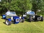
My Tiger 700 goes, stops, and turns, so I have achieved the "GoKart" milestone!

I'm now in to the "Refine and Enhance" phase. In other words, Fix / tweek the car to make it truly roadworthy and robust. Then add the items needed for DOT registration like seat belts, lights, horn, etc. My first step was to order a bunch of new parts. While I wait the parts to arrive, I thought it would be a good time to catch-up on my LoCost forum posts.

To see video #14 on the completion of my chassis -> Click Here

My CAD design guided the construction of the chassis, but some measurements were adjusted as I went. For example:
  • I added 50mm (2"mm) to the wheelbase to ensure I had enough leg room
  • The attachment points on the rear subframe had changed, so I adjusted the chassis accordingly

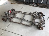
Every pound counts in this vehicle, so most of the chassis is constructed of thinner .065" wall tubing. The FEA-BLE modeling showed that chassis design is inherently strong, so this lighter tubing could be used. In fact the finished chassis is ultra-stiff. I used a variety of tubes and gussets:
  • 1.5" x .120" round tubing - This is a typical dimension for a roll-bar tubing. I had a full roll-bar left from an earlier project, so I just cut off one corner of it for the Tiger 700.
  • 1" x 1.5" x .065" rectangle tubing - Square or rectangular tubing resists bending better than round tubes. I used the rectangular tube to surround the cockpit to provide greater impact resistance in case of an accident.
  • 1" x .065" round tubing - Round tubing is lighter per running foot when compared to square or rectangular tubes. The rest of the chassis structure used the 1" tubing.
    [list=]
0.5" x .065" round tubing - Smaller diameter tubes are strong in short lengths. I used the 0.5" tube for short braces, seat frame, etc.
[*].083" x 2" x 2" triangular gussets - Steel plate gussets add considerable strength to tube joints. I used gussets where there wasn't space for a 0.5" round tube brace. [/list]

Now that I have the central chassis in place, you can better see the direction it's heading. Its been difficult to see the big picture until now because I followed a different approach. Most LoCost builders start by building the central chassis and then work out to the suspension. I have always read that good handling starts with the tire patch and then works back to the chassis, so that was the sequence I followed.
  • I started by thinking about my spindle, hub adapter, wheel and tire as a single component. This is all un-suspended weight, so wanted it to be a light as possible. I used Miata hollow spoke wheels (10lbs), the lightest 14" tires I could find (12-15lbs), aluminum hub adapters (lathed down to 1/2 their original weight), and the Raptor spindle, hub, brakes are feather weights. The wheels, tires and hub adapters were chosen so they work in concert with the spindle's kingpin angle, to produce almost no scrub radius.
  • The combination of the upper control arms, lower control arms, and the rack & pinion were the next component to design all together. Now that the location of the spindle's upper/lower control arm ball joints are known, the length and angle of the control arms can be designed to achieve the proper Roll center and lean camber angles. The inner pivot points of the control arms need to align with the rack & pinion's steering rod universal joints as well.
  • The next step is the structure for the upper/lower control arm pivot points and for the spring mounts.
  • Then tie the suspension hard points to the rest of the chassis in a way that provides overall torsional and load carrying strength
  • Now repeat the steps above for 20+ iterations to evolve your design into a well balanced and build-able plan...Nothin' to it :BH:

The engine is a single cylinder 700cc engine, so there will be some vibration. The chassis design incorporates polyurethane isolators to minimize the vibration that the driver feels. There are 6 isolators to the rear subframe and 4 to the front subframe.
Attachment:
Extreme drawings.jpg


You do not have the required permissions to view the files attached to this post.


Top
 Profile  
Reply with quote  
PostPosted: August 1, 2018, 10:40 am 
Offline

Joined: May 29, 2018, 8:43 am
Posts: 184
Location: That point where the humidity and the temperature combine forces to destroy all that is good
That's a wicked looking little beast!

_________________
Who knew so much time involved in building a car is spent simply staring at the pile of parts you've accumulated?


Top
 Profile  
Reply with quote  
PostPosted: September 21, 2018, 2:56 am 
Offline
User avatar

Joined: March 19, 2011, 10:22 am
Posts: 2392
Location: Holden, Alberta, Canada
Update required, been a while!

_________________
Perry

'If man built it, man can fix it'
"No one ever told me I couldn't do it."
"If you can't build it safe, don't build it."

Perry's Locost Super Che7enette Build
Perry's TBird Based 5.0L Super 7 L.S.O
Perry's S10 Super 7 The 3rd
Perry's 4th Build The Topolino 500 (Little Mouse) Altered
Perry's 5th Build the Super Slant 6 Super 7
Perry's Final Build the 1929 Mercedes Gazelle


Top
 Profile  
Reply with quote  
PostPosted: September 21, 2018, 8:17 am 
Offline
User avatar

Joined: May 29, 2015, 6:09 pm
Posts: 120
Location: Charlotte
Thanks for the bump...Yup, I'm delinquent!

Just returned from a 3 week bicycle ride between Kansas City and Santa Fe, NM. It was about 800 miles and a great time. It's part of a longer journey across the u.s. that I broke into 4 sections. On Earlier bicycle rides , I started in Wilmington North Carolina on the Atlantic coast and rode to Knoxville, then I rode Knoxville to Kansas City. I now only have the last section from Santa Fe to Los Angeles to complete my Coast to Coast bicycle trip next year.

The Raptor 700 is running and driving and I've made some progress. I'm currently focusing on the electrical and tweaking some of the details. I'm trying finish the underlying chassis details ASAP, so I can move on to sculpting the body in the cool Fall/winter months.

I'll try to catch up on my forum posts as quickly as I can. Unfortunately I have other commitments over the next 4 weeks. I have a week long training conference in Palm Springs California on the SketchUp 3D modeling tool and a week of vacation with my wife.

Busy...busy...busy


Top
 Profile  
Reply with quote  
PostPosted: February 14, 2019, 10:40 pm 
Offline
User avatar

Joined: May 29, 2015, 6:09 pm
Posts: 120
Location: Charlotte
I'm baaaack!

Sorry for the long dead time on my forum posts. I overwhelmed my PC with all the videos and photos I was editing. I got a new more powerful PC for Christmas, so I'm up and running again.

Even though its been radio silence on this thread for 7 months, I have continued the construction of my Tiger 700 and I have been capturing video along the way. I have a long backlog of videos to edit and roll out over the next few months.

Here is video episode 15 -> Click here

Seat and Safety Harness
The chassis is finished now and I added the seat and floor. The chassis was designed so the tubes outline the seat to form its frame. I then simply fabricated .040" aluminum sheet to stretch between the frame tubes to form the seat and floor. Its plenty strong and very light weight. The down side is that the seat position is not adjustable. Maybe sometime in the future, I may modify the pedal assembly to be adjustable. I added a 4-point safety harness, so its ready to test at higher speeds now.
Attachment:
Seat and floor.jpg

Attachment:
Seat Rivets.jpg


Rerouting the Exhaust
The Raptor 700 muffler is routed along the right side of the tail frame. Since I'll be enclosing the tail with a fiberglass body, the muffler was in an awkward position that would stick outside the body. I decided to reroute the muffler so it ran inside the tail frame and exits at the center of the tail. After examining the many bends and angles in the exhaust (along with a few beers and a lot of head scratching), I found a seam in the pipe that was the answer. By simply cutting the seam and re-clocking it, the muffler would twist into the direction I needed and barely clear the suspension and frame. The previous owner of the Raptor 700 replaced the exhaust with a titanium unit. So after marking the re-clocked position, I took the exhaust to a shop that specializes in titanium welding. Just $50 later I had an exhaust that perfectly fits my build project.
Attachment:
exhaust before.jpg
Attachment:
exhaust seam reclock.jpg


You do not have the required permissions to view the files attached to this post.


Top
 Profile  
Reply with quote  
PostPosted: February 15, 2019, 6:00 pm 
Offline
User avatar

Joined: October 10, 2010, 10:26 am
Posts: 2041
Location: Guadalupe, CA
This is a fun, innovative build.. looking forward to how you make the body 8)

If you ever think you want more out of the motor it’s there for the asking... I have a 105mm 11:1 piston (CP) in my Raptor, and it really woke it up, and it’s on 91 (pump gas).. fun and lots of torque... The previous owner had a 13:1 piston in it, which was too much in my opinion... ran very finicky and needed race gas.. stepped down to the 11:1 and love it..

ccrunner

_________________
Dean

1972 Honda N600 Restomod "ccrunner's N600 VFR800 repower"

1963 Volvo P1800 Restomod
http://locostusa.com/forums/viewtopic.php?f=36&t=16309

1959 Berkeley SE492 Restomod...
viewtopic.php?f=36&t=19397

"ccrunner's 1960 MGA coupe Restomod" found on MGExp.com


Top
 Profile  
Reply with quote  
PostPosted: February 16, 2019, 7:54 am 
Offline
Automotive Encyclopedia
User avatar

Joined: December 22, 2006, 2:05 pm
Posts: 8041
I like this build also. Maybe you have special rules in your state for replicas that would make the atv bits a non-issue. Speaking of having episodes, I request, nay, demand to see this puppy in action! :shock: :cheers:

I can see the conflicts that led to the location of the fuel tank and filler. Here is another option that might appeal to you but the tank will have to be custom. Designed for a vented cap (air in and out versus just in). If the cap only allows air in, use a separate rollover valve, keep the standpipe on the filler neck, but omit the small hole.

Out of the line of sight, doesn't interfere with the pedals, maintains access to pedals, coilovers, and their reservoirs. Provides expansion space, reduces slosh, and keeps the outlet covered. I'm thinking .080" 6061 with 1/4" mounting ring and 3/8" block for the outlet for a pipe thread fitting. May want to rework the coilover mounts for clearance. You could make the tank wider at the top to overhang the subframe mounts and extend it forward for more capacity. Speaking of the mounts, you used hardened bolts but there is no positive stop except for the stiffness of the nylon sleeves that look pretty thin. A 1/4 wall uhmw sleeve would be a good compromise between a steel or aluminum inner sleeve and what you have now.

You could also put the radiator up front then use the space under the seat for storage like a glove box.

Seat could use upholstered squabs/cushions with velcro sewn to the back with adhesive back velcro on the metal, like airline seat bottom cushions.

An elbow in the flat base plate for the air filter mount would be easy to fab without compromising flow and will get the filter off the exhaust. Just pie wedges in the side view with a filler strip across the bottom. Cut the bottom and sides, then bend the center flap the air filter mounts to up for the desired clearance, cut paper patterns to fill the gaps. Happy to draw a picture if my words fail to convey. Also, the filter (cotton gauze) should be oiled just like the original.


You do not have the required permissions to view the files attached to this post.

_________________
Miata UBJ: ES-2074R('70s maz pickup)
Ford IFS viewtopic.php?f=5&t=13225&p=134742
Simple Spring select viewtopic.php?f=5&t=11815
LxWxHt
360LA 442E: 134.5x46x15
Lotus7:115x39x7.25
Tiger Avon:114x40x13.3-12.6
Champion/Book:114x42x11
Gibbs/Haynes:122x42x14
VoDou:113x44x14
McSorley 442:122x46x14
Collins 241:127x46x12


Last edited by Miatav8,MstrASE,A&P,F on December 22, 2019, 6:43 am, edited 1 time in total.

Top
 Profile  
Reply with quote  
PostPosted: February 16, 2019, 12:18 pm 
Offline
User avatar

Joined: March 30, 2011, 7:18 am
Posts: 1615
Location: central Arkansas
Is that 1x2 tubing across the front of the cockpit?

They make push-in plastic plugs in 1x2" as well as 1x1".

https://www.amazon.com/Rect-Tubing-Plug ... B00ANN89LG


Top
 Profile  
Reply with quote  
PostPosted: February 17, 2019, 10:09 pm 
Offline
User avatar

Joined: May 29, 2015, 6:09 pm
Posts: 120
Location: Charlotte
ccrunner wrote:
This is a fun, innovative build.. looking forward to how you make the body 8)

If you ever think you want more out of the motor it’s there for the asking... I have a 105mm 11:1 piston (CP) in my Raptor, and it really woke it up, and it’s on 91 (pump gas).. fun and lots of torque... The previous owner had a 13:1 piston in it, which was too much in my opinion... ran very finicky and needed race gas.. stepped down to the 11:1 and love it..

ccrunner

I'm in somewhat of a dual mode at the moment. I'm trying to catch up on my post and the videos, while I'm actually well ahead of that point right now. In fact, I started building the body this week. More to come on that later.


Top
 Profile  
Reply with quote  
Display posts from previous:  Sort by  
Post new topic Reply to topic  [ 155 posts ]  Go to page Previous  1 ... 3, 4, 5, 6, 7, 8, 9 ... 11  Next

All times are UTC - 5 hours [ DST ]


Who is online

Users browsing this forum: No registered users and 22 guests


You cannot post new topics in this forum
You cannot reply to topics in this forum
You cannot edit your posts in this forum
You cannot delete your posts in this forum
You cannot post attachments in this forum

Jump to:  
POWERED_BY