I'm back. All my posts were wiped out when LocostUSA had to restore to two years back. I see they finally were able to restore my old posts with comments but all the attachments were lost. I have restored the most important pictures. Let me know if you need more.
I forgot to thank my neighbor Mike who helped me remove the body from the Miata. He has also given me some great tips. He happens to be a mechanic by day and car project enthusiast by night. He has a number of hot rods, performance car mods and motorcycle projects under his belt. What are the odds I would move next to this guy?
Here is a summary of what has happened while I was gone.
- I Removed the remains of the body, cut it up into 9 pieces, took them to Tucson Iron and Steel in my RAV 4 (two trips) and got a whopping $13 dollars. But that price was fair as scrap sheet metal is only going for $50 a ton here.
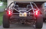
- I have been spending my time cleaning up the roller skate and measuring it.
- I found a Tucson waterjet shop that says they will cut down my windshield for a reasonable price if I bring them a CAD file of the cut. That makes sense as I'm sure much of the high cost of waterjet cutting is creating that file.
- I made a CAD model of the roller skate so I can design the chassis on it.
DetailsAs I am working alone, I created a tool to help hold the tape measure while I measure the roller skate. It is just a 3D printed part. The bottom fits snuggly in a mounting hole and the top has a slit to hold the end of the tape measure. The slit also makes a handy reference line for the other hole. Note that there is a hole in the middle of the top. This holds a dowel alignment pin (sharp point). I will add the pin later when I want to mark the exact center of the mounting hole on the mounting plate of the new chassis.
Attachment:
Tool copy.jpeg
Using a combination of a tape measure, my 3D tool, dowels and two tripod mounted laser levels, I measured the relative positions of the frame mounting points. I was able to check some of them against measurements of the body mounting points in the service manual. Sometimes I was able to match those numbers within a few millimeters. Other were hard to make with my inexpensive lasers and may be off up to 10 millimeters. But my plane Is to check the fit of each part of the chassis as I build it and make any adjustments as I go.
Note that some parts of the model are well done and show a lot of detail while others are very simple. That’s because I got the detailed parts, suspension mainly, from [url]GrabCad.com[/url] — just search for Miata. But I could not find existing models for the subframes, drive train, etc. So I created them but only added the detail required to assure that the chassis rails would clear critical parts. Consider them mere volume models. I did this because a) I am an amateur at CAD so it would take a long time to make realistic parts and b) it's not necessary for my project and c) I want to get the model done and get on to cutting and welding steel.
Here is the roller skate model as it sits in my garage. The mounting holes are shown in red boxes. These are the important points and the volumes of the parts I have to avoid.
Attachment:
Top of scate board.png
Here is the same model but I have added other major elements like radiator, seats, etc. I will have to add a gas tank but I’m debating about using the original tank or buying a fuel cell.
Attachment:
Scateboard with stuff.png
Next I’ll design a chassis and post that for comment. This will probably take a week or so as I have a lot of alternative designs to consider.