LocostUSA.com

Learning how to build Lotus Seven replicas...together!
It is currently April 28, 2024, 1:41 am

All times are UTC - 5 hours [ DST ]


Post new topic This topic is locked, you cannot edit posts or make further replies.  [ 25 posts ]  Go to page 1, 2  Next
Author Message
PostPosted: September 19, 2011, 11:49 pm 
So i posted a while back about my project. It started over two years ago when I was just 19. I wanted to build a bike engined car. I found a Honda 1000RR motor and set to work. My first frame was way overengineered and had several design flaws. I got it as far as a rolling chassis before I decided to start over on the frame. I started building a new frame out of 1" square tube and got a good start on that, but then again there were a couple things I wanted to change about it. I also loved the look of curved round tube, but had no idea where to even start. I ended up moving, then getting a traveling job with the railroad, and the car sat on hold for nearly a year. I finally settled in to a local job, and found myself a shop to rent. After making a build table and putting in a 220v outlet for my welder, refilling my argon, and bringing all my tools in, I set myself to work on the new frame--made from 1.5" x.120 round tube curved and much more stylized. The goal is to have the car road legal by March 9, 2012, so I will be pounding away throughout the winter.

Lets get to some pics:

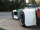
this is how far I got on my first frame:
Image

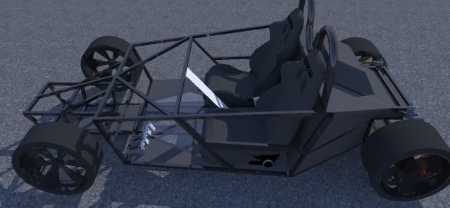
then I drew this up in sketchup:
Image

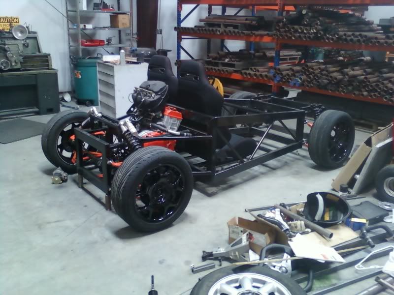
and got it this far:
Image

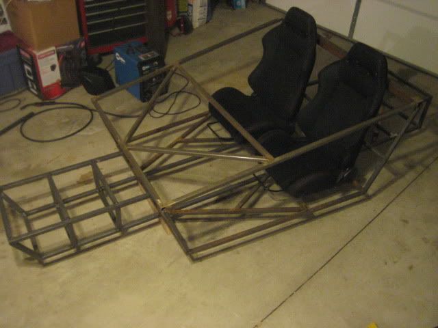
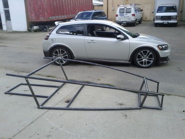
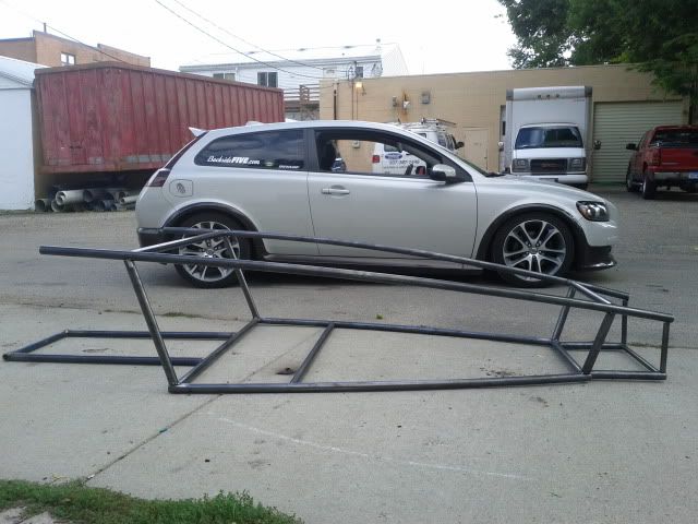
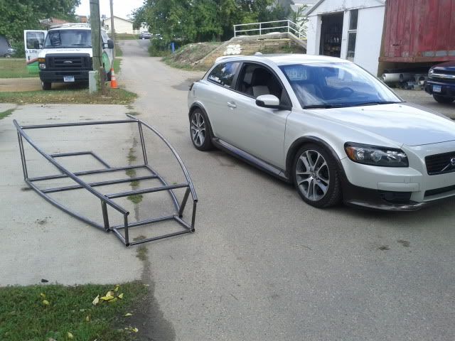
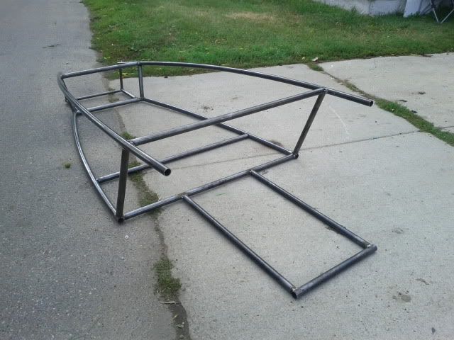
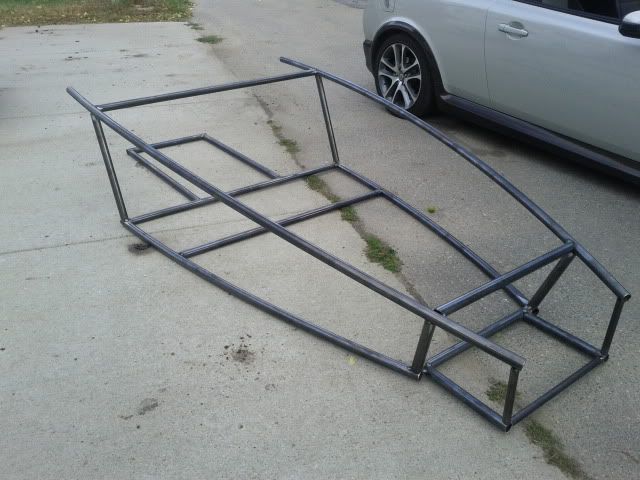
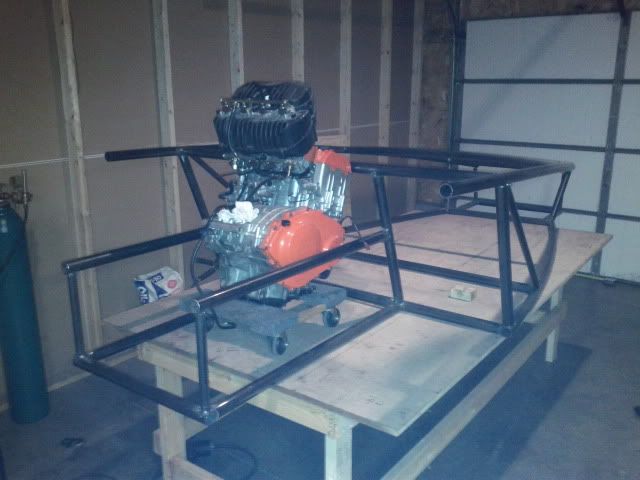
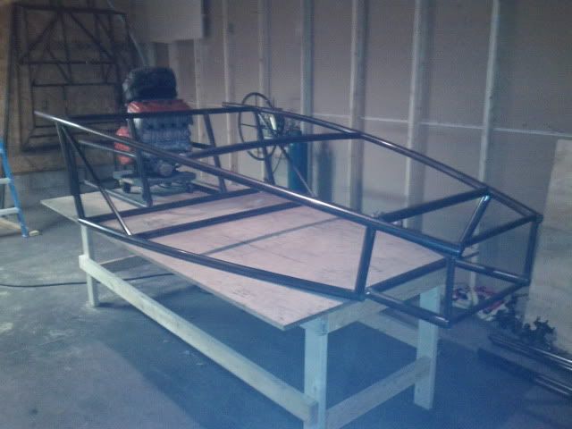
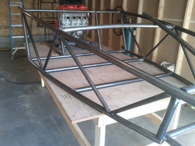
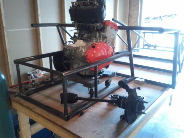
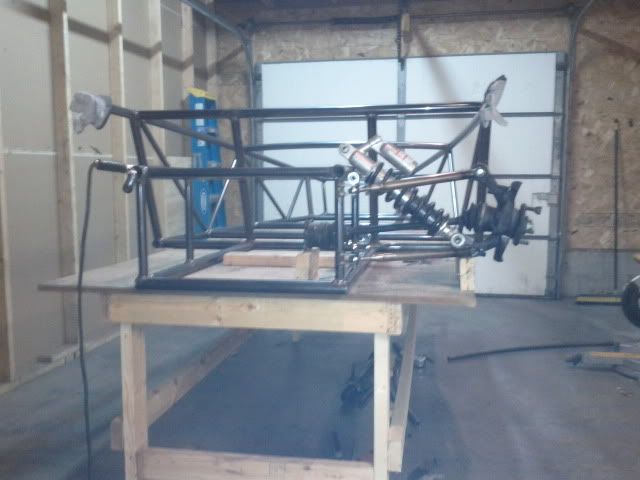
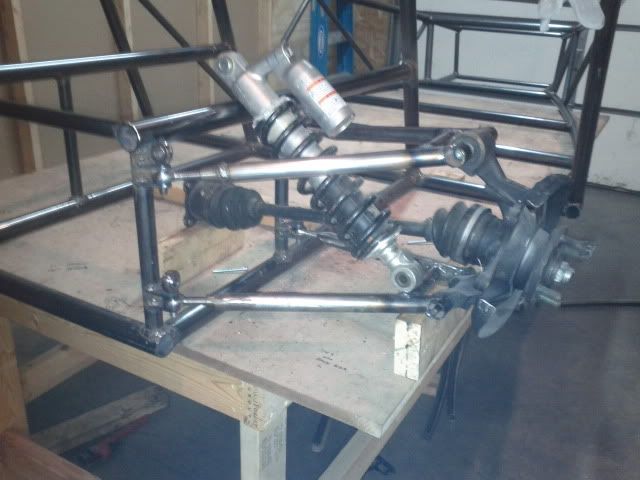
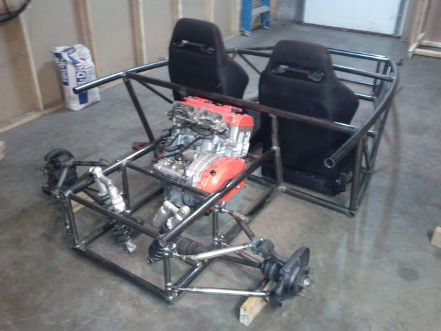
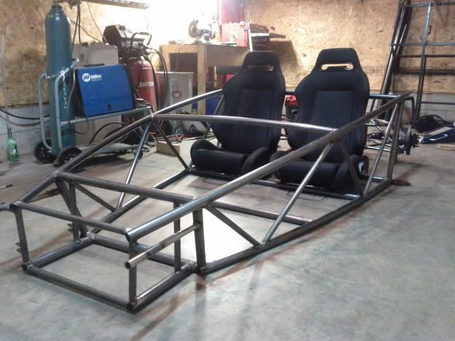
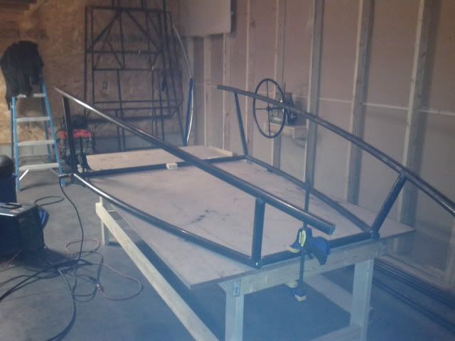
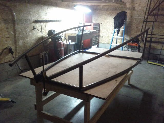
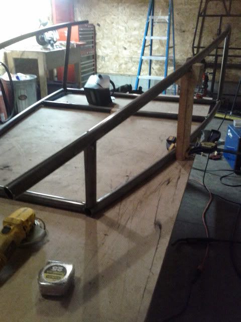
then I got my new shop, and ive been working on the new frame for about two weeks now. this is how the car sits now:
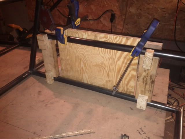
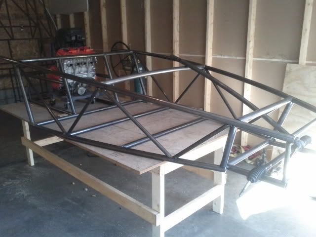
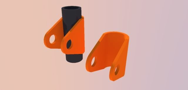
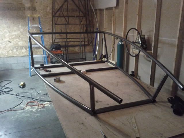
Image

Image

side bar jig:
Image

Image

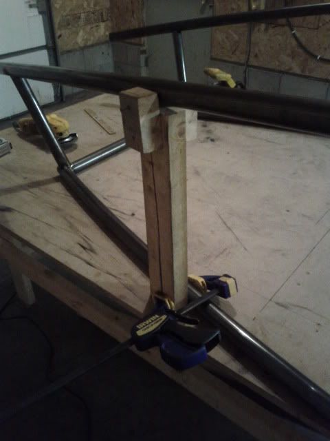
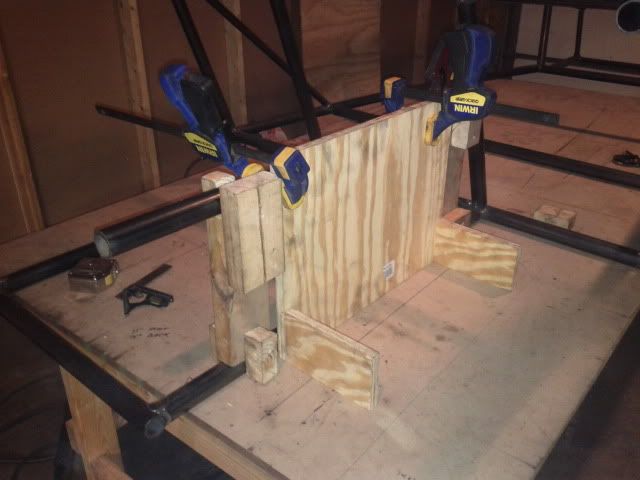
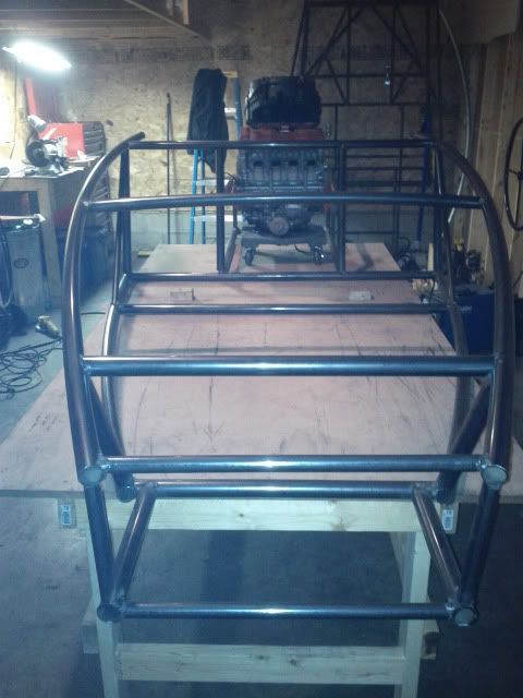
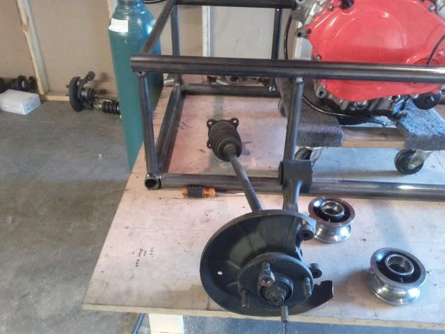
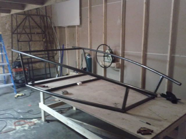
and the rear bulkhead crossmember in:
Image

Image


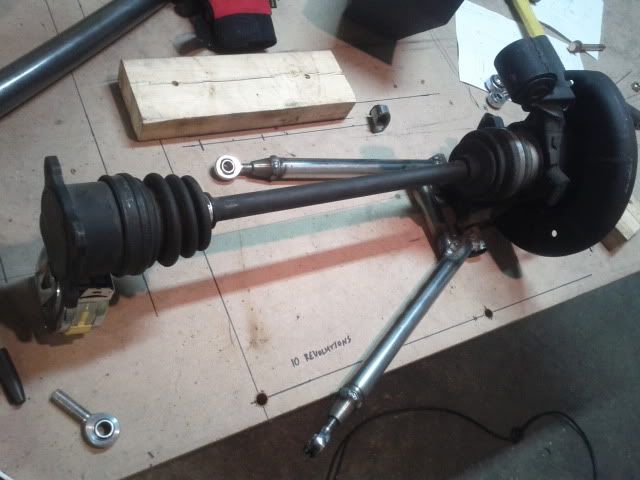
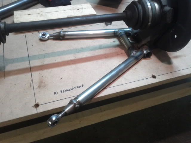
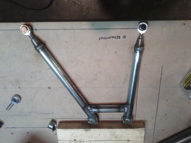
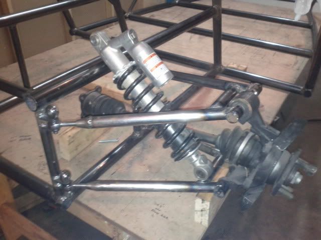
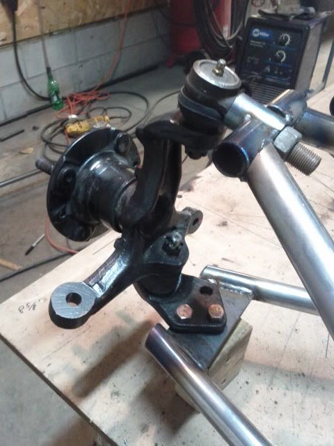
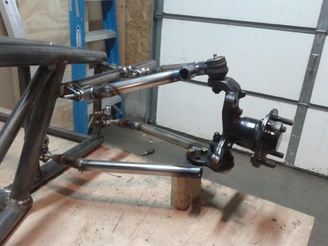
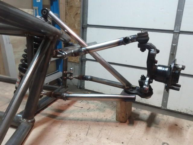
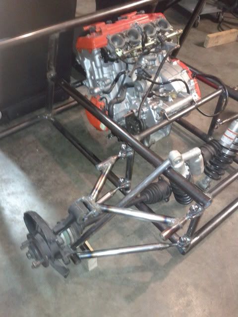
it feels so nice to be working on the car again! looking to do chain drive rear end, LSD. I already have full miata running gear. Double wishbones all around with coilovers from a Kawasaki Teryx. Two seater, mid engine.


Top
  
 
PostPosted: September 20, 2011, 1:23 am 
Offline
User avatar

Joined: February 20, 2008, 1:24 am
Posts: 294
Location: Mahomet, Il
I like where this is headed!

_________________
MG midget bodied Locostish car in progress


Top
 Profile  
 
PostPosted: September 20, 2011, 5:37 pm 
got more done today. got the front subframe tacked in and the lower rails of the engine bay tacked in. got another crossmember in too.

put it outside next to my daily driver for reference. heres the progress:

Image

Image

Image

Image

Image


Top
  
 
PostPosted: September 20, 2011, 6:01 pm 
Offline
Toyotaphobe
User avatar

Joined: April 5, 2008, 2:25 am
Posts: 4829
Location: Fort Worth, Texas
Gee, and I liked your first try.

_________________
mobilito ergo sum
I drive therefore I am

I can explain it to you,
but I can't understand it for you.


Top
 Profile  
 
PostPosted: September 24, 2011, 10:45 pm 
more progress...dash bar is in place, rear engine bay is nearly complete. started on the angled support bars on the sides (i jump around when im working...)

jig to square up the engine bay (super high tech stuff here):
Image

Image

Image

Image

Image

tomorrow is my day off so i should make a lot of progress then too


Top
  
 
PostPosted: September 25, 2011, 7:11 pm 
got some more done today. rear frame is finished off, second floor bar is in, and the crossmembers done. also modeled my suspension mounts in sketchup:

Image

Image

Image

Image

Image


Top
  
 
PostPosted: October 5, 2011, 12:05 pm 
Got a little more work done---having trouble sourcing those brackets i designed. So i've started some final welding and played around with rear lower control arm designs:

Image

Image

Image

and these are what I need--I'd rather buy them than build them. anyone seen anything like this somewhere? needs to wrap around 1" OD tube

Image


Top
  
 
PostPosted: October 5, 2011, 1:02 pm 
Offline
User avatar

Joined: July 17, 2008, 9:11 am
Posts: 6416
Location: West Chicago,IL
A&A Mfg has tabs like that.

http://www.aa-mfg.com/pdshop/shop/item.aspx?itemid=412

This one is for 7/8" dia tube and a 3/8" hole for the Heim joint but they must have others. I didn't look further.

They literally have hundreds of different kinds of brackets, maybe thousands. They could put BUBBA out of work if JD didn't already do that.

If they don't have exactly what you have designed, then maybe in a couple of hours of searching, you could find something else that would work. Generaly, when you design something yourself, expect to have to fabricate it yourself or pay someone else to fab it for you. You probably won't find exactly what you thought up.

_________________
Chuck.

“Any suspension will work if you don’t let it.” - Colin Chapman

Visit my ongoing MGB Rustoration log: over HERE

Or my Wankel powered Locost log : over HERE

And don't forget my Cushman Truckster resto Locostusa.com/forums/viewtopic.php?f=36&t=17766


Top
 Profile  
 
PostPosted: October 5, 2011, 1:46 pm 
Offline
User avatar

Joined: June 10, 2011, 6:27 pm
Posts: 29
Location: Milwaukee, WI
Awesome! I hope that I don't have to/decide to start over when I get my rolling chassis lol (about a month)

Keep at it!

_________________
"I'll probably get this build done in a year or two..." - me. Also quite wrong! Haha

www.ruggedvid.com - Airborne Recorders, Cameras, and HD Video Systems


Top
 Profile  
 
PostPosted: October 5, 2011, 1:50 pm 
Offline
Mid-Engined Maniac

Joined: April 23, 2006, 8:26 pm
Posts: 6421
Location: SoCal
rx7locost wrote:
...Generaly, when you design something yourself, expect to have to fabricate it yourself or pay someone else to fab it for you. You probably won't find exactly what you thought up.

^This. I had to chuckle when I saw that you designed the bracket, then couldn't find where it was sold. You have to find what's already available and then decide if it can be made to work. Otherwise, as noted, you have to get it fabricated.

_________________
Midlana book: Build this mid-engine Locost!, http://midlana.com/stuff/book/
Kimini book: Designing mid-engine cars using FWD drivetrains
Both available from https://www.lulu.com/


Top
 Profile  
 
PostPosted: October 5, 2011, 5:39 pm 
well i understand. I guess I didnt really design it...just kind of drew up what i needed. I would assume SOMEONE out there has something like that, as its a fairly simple design with very general dimensions. I guess I was wrong. I might just suck it up and weld tabs on...


Top
  
 
PostPosted: October 14, 2011, 5:58 pm 
got my inboard suspension mounts welded on one corner last night. mocked up the suspension. I havent made my upper control arms yet, so I only have lowers and used both of those for mock up purposes, hence the crazy positive camber and equal length arms.

Image

Image

Image

sorry for crappy phone pics


Top
  
 
PostPosted: November 19, 2011, 10:54 pm 
update:

front suspension was mocked up using butt welded tube, and then had tube bent after finalizing the design. also did a lot more finish welding and got a few engine mounts in. got a new saw and shortened my manual civic rack.

Image

Image

Image

Image

Image

Image

Image

Image


Top
  
 
PostPosted: November 20, 2011, 1:13 pm 
Offline
User avatar

Joined: April 12, 2010, 5:40 pm
Posts: 2081
Location: san francisco bay area
gecko1000 wrote:
>>>>>>>>got a new saw and shortened my manual civic rack.


OOOOhh, could you go a bit more in depth with this part?
For example, what's the total travel of the rack lock to lock and which ratio do you have?
Were you able to drill and tap the shortened rack or did you weld on a relocated end?
There was a question raised a few days ago about rear steer racks. ...
I thought the 98 "R" rack looked pretty interesting at <3 turns lock to lock but don't know the total travel.

_________________
"There are times when a broken tool is better than a sound one, or a twisted personality more useful than a whole one.
For instance, a whole beer bottle isn't half the weapon that half a beer bottle is ..." Randall Garrett


Top
 Profile  
 
PostPosted: November 20, 2011, 2:08 pm 
i put tape between the upper and lower pivot points for the front suspension, then did some math to figure out how wide i needed the rack to be, pivot to pivot. I determined it needed to be 3" shorter than what it was for proper geometry. So i threw it in the saw, and cut it in half, straight through the shell and the solid bar. then cut three inches off of each and grooved and welded everything back together, ensuring it was true


Top
  
 
Display posts from previous:  Sort by  
Post new topic This topic is locked, you cannot edit posts or make further replies.  [ 25 posts ]  Go to page 1, 2  Next

All times are UTC - 5 hours [ DST ]


Who is online

Users browsing this forum: No registered users and 23 guests


You cannot post new topics in this forum
You cannot reply to topics in this forum
You cannot edit your posts in this forum
You cannot delete your posts in this forum
You cannot post attachments in this forum

Jump to:  
POWERED_BY