LocostUSA.com

Learning how to build Lotus Seven replicas...together!
It is currently April 20, 2024, 1:48 am

All times are UTC - 5 hours [ DST ]


Post new topic Reply to topic  [ 195 posts ]  Go to page Previous  1, 2, 3, 4, 5 ... 13  Next
Author Message
 Post subject:
PostPosted: January 9, 2009, 3:50 am 
Offline
User avatar

Joined: July 22, 2007, 10:58 pm
Posts: 388
Location: Zagreb, Croatia
Blackbird wrote:
But, what about the poor Lancia?
The Delta Integrale is still one of my favorite street cars.

Good job on the middy 8) .

moti


I sold the lancia to a friend, he allready has one and is restoring mine..

I got a chance to buy a almost new mitsubishi EVO 9, and considering I never thought I could afford one, I just had to do it... Lancia had to go, as well as my Peugeot 205 GTI and 306 GTI.... (wife could not stand any more cars..)... it was worth it though.. :D


Top
 Profile  
Reply with quote  
 Post subject:
PostPosted: January 12, 2009, 3:16 pm 
Offline
User avatar

Joined: July 22, 2007, 10:58 pm
Posts: 388
Location: Zagreb, Croatia
ok, V2.. :)
So the decision was made to have a cross brace between the front inner suspension pickup points. Due to the fact I am running 13 inch wheels my upper suspension mounts are close enough to the lower ones as not to have enough space for my feeet. This means I had to put the front suspension even further forward.
First I had a seat in my “simulator” too see how much space I need in the cockpit. This fixed the distance between the front suspension and the bulkhead.

Image


Having feet and pedals behind the front suspension meant that I can use the space for something else.

Using it for the steering rack was interesting as this would give me good ackerman with simpler front uprights (pickups can be inboard instead of outside of the steering centerline). However, the rack needs to go really low, so there was no space for the column, and I do not want to have it between my feet.
So I decided to use the space for the front shocks and the battery. Steering rack will be in the absolute front of the car.


Top
 Profile  
Reply with quote  
 Post subject:
PostPosted: January 12, 2009, 3:17 pm 
Offline
User avatar

Joined: July 22, 2007, 10:58 pm
Posts: 388
Location: Zagreb, Croatia
So to finalise the suspension.


Front
Objectives were, long suspension arms, to keep low working angles on the joints. Zero roll centre movement in all directions. No positive camber at any point.

120 mm ride height, which ended up being 100 mm in fact as I was calculating with tube centreline, and with 40 mm tubing, I loose 20 mm clearence.. :)

This gave me front lower suspension pickups at 160 mm above the ground, or 40 mm above the lowest frame point.

I started with about 1.5 deg camber at ride height, and have some negative camber at 3 deg roll.

I managed to package in long coilover dampers, so that I could use 1:1 motion ratio.

The front suspension diagram and most important curves are on the pic.

Image


Top
 Profile  
Reply with quote  
 Post subject:
PostPosted: January 12, 2009, 3:18 pm 
Offline
User avatar

Joined: July 22, 2007, 10:58 pm
Posts: 388
Location: Zagreb, Croatia
Rear suspension.

As far as geometry goes, it started the same as in the front. I did play a bit with the width of the pickup points to get the rollcentre up a bit, and adjusted the upper ones to neutralise the newfound ROC mowement.
However there was a different problem.

In the foront I use A arms with 400 mm between the front and rear pickups. Having run the geometry trough the FEA, I found out that I was going to be OK with 20 – 25 x 1.5 mm tubing. Forces I used for the FEA were 5,4,3 G (longitudinal, vertical, side) and for the individual wheel load I used ½ projected mass because I thought that in worst case I could have enough force transfer to unload the inner wheel completely.. Better safe than sorry.

However, in the rear the distance between the pickups is dictated with the position of the engine. Front pickup sits right behind the engine. The crossmembers serving as mounts for the engine and dampers.
Rear pickups have to clear the sprocket, which will have to be large enough so that I can gear the car for only 200 km/h. At the same time, I wanted to push the engine as far forward as possible, but keep the rear axle a bit further back, while staying within a reasonable wheelbase. The reason for this is first and foremost the weight balance, and then the chainline which can suffer when you mount the sprockets too close.

This resulted in suspension pickups being too close for comfort, especially for the lower A arm, because the loads might be too high, and it could bend too much. Instead of making new lower pickups somewhere around the engine, I decided to attach them directly to the bulkhead, to keep the weight low.

This changes the geometry a bit, but with the adjustment to the upper front mounts I got the geometry in order. See pic.

Image


As for anti squat and anti dive, I did not implement it as it is too complex, but I am leaving some space in the pickups to move the pickups up and down a bit, so might play with it later.


Top
 Profile  
Reply with quote  
 Post subject:
PostPosted: January 12, 2009, 3:20 pm 
Offline
User avatar

Joined: July 22, 2007, 10:58 pm
Posts: 388
Location: Zagreb, Croatia
Here is the V2 frame. Very similar to the V1, just a lot longer (almost 200 mm) and with a crossmember between the front rear suspension pickup just in front of the pedals.

Looking at it you are right to ask “how do you get the engine out”? :)
I was thinking about it, wanted to do removable lower tubes below the engine at first. Then I noticed that the rear part of the chassis is, in reality, connected at 4 points which I can, at some effort, make separable. Exactly how I’ll do it, you will soon see, it will be a b%$^# to weld but should look nice :)
In the pic, the rear part that separates is in blue. It holds the engine and rear suspension. The main chassis holds the complete safety cell including the rear triangled that support the roll hoop.

Image

Also notice the suspension pickups. I do not plan on welding the brackets onto the frame. Instead, I am using 45 mm x 1.5 mm tubing inside which will be suspension pickups. How exactly this will work, you will soon see as this is the first thing I have to do when fabricating... :) I know I will have trouble with wrapping but I just like this idea and would like to make it a design feature.

Image

Image

Image

Image

The tank will sit behind the driver, as I expect the COG to be somewhere there.. :)

Image


Top
 Profile  
Reply with quote  
 Post subject:
PostPosted: January 12, 2009, 3:21 pm 
Offline
User avatar

Joined: July 22, 2007, 10:58 pm
Posts: 388
Location: Zagreb, Croatia
Now comes the part for which FEA is ideal.
I did a first set of numbers and got a bit of a dissapointment. 69 kg and about 4000 nm/deg (2950 lbft/deg). Now, this is not exact mass, as I did not remove parts of the tube that were inside of the joints.. but I use it as indication.

One more thing I used, and which I would suggest anyone doing this analysis is to calculate speciffic stiffnes.. i.e. torsionall stiffness / weight

So for the start I got 4000 Nm/deg, 69 kg which gives me a factor of 58.

Frame stiffness goes down with it’s length, and the weight goes up, so I was paying the price for comfort. :)

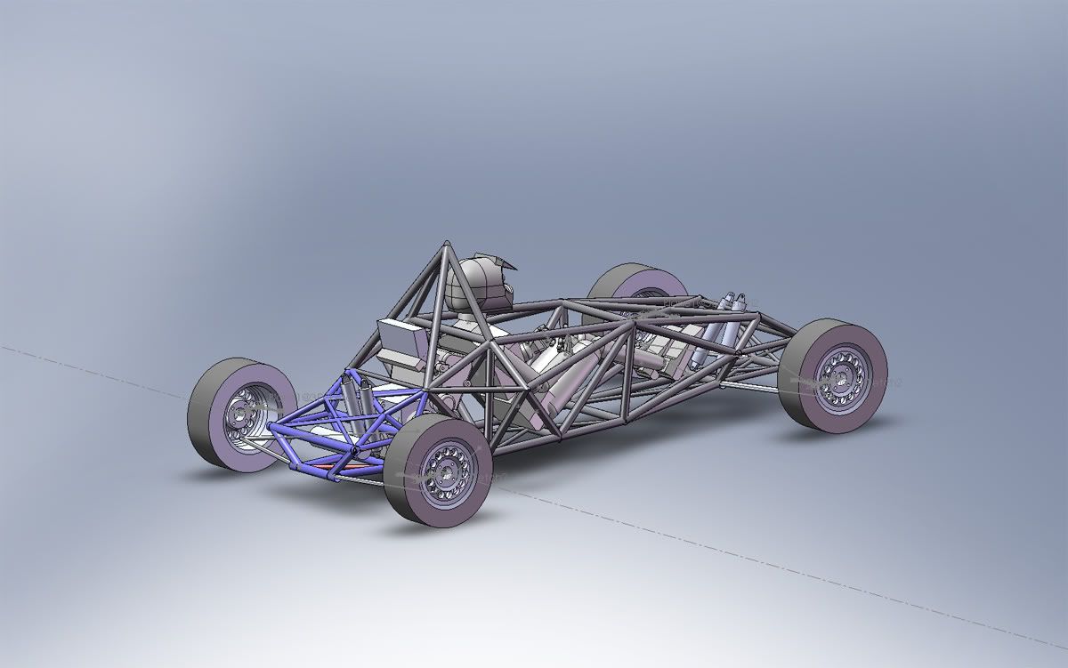
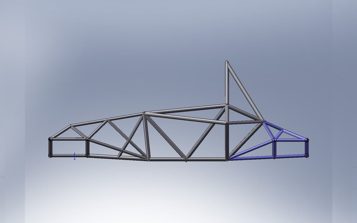
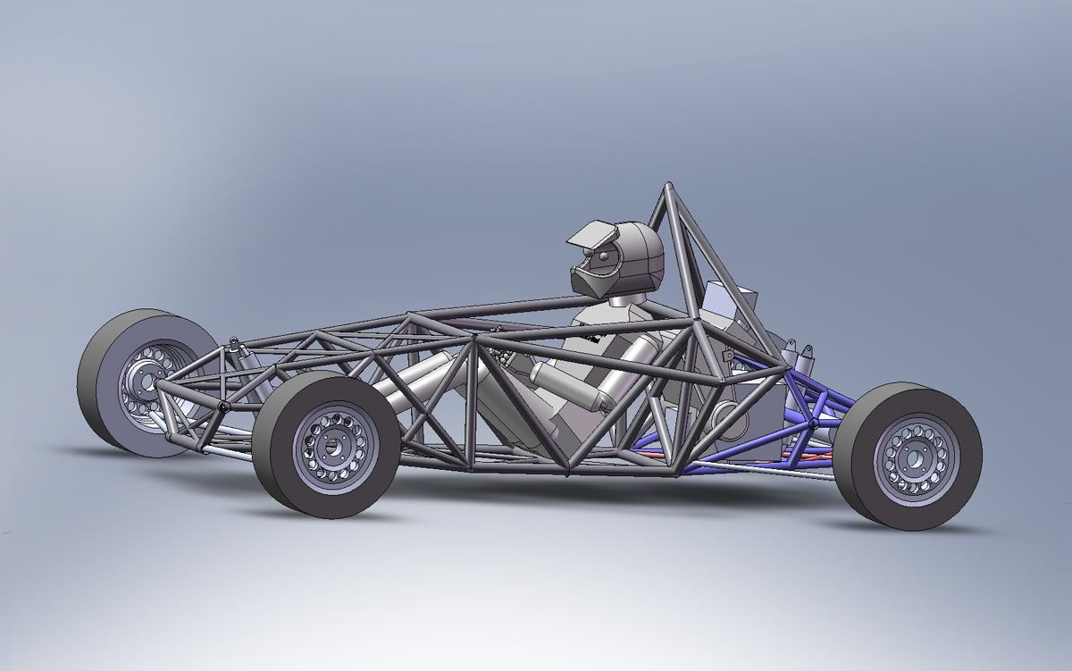
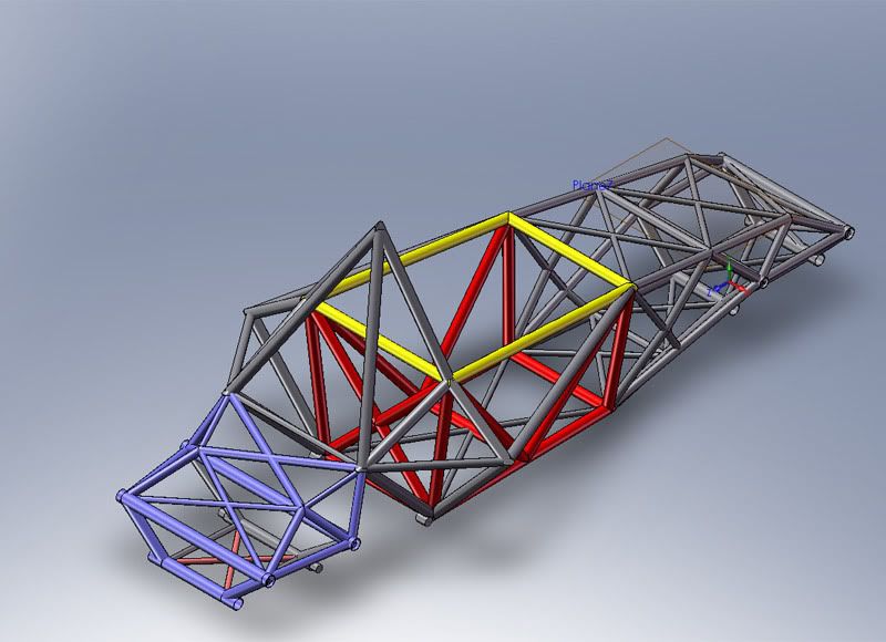
Looking at the FEA pics, I coud see where most of the twist was present.
There were 3 main areas to be improved.
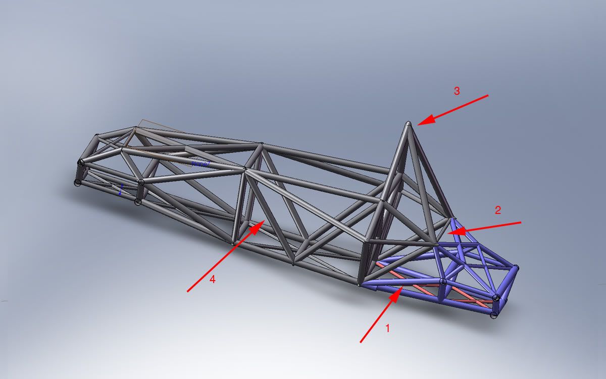
1. Front section, from the nose to the driver opening.
2. Driver space that is open from above. It gains most of it’s stiffness from the triangles on the outside, however I wanted to know if I could find more.
3. Rear section. Now, this is not modeled right in the FEA as I did not include the engine. It wil lbe stiffer with the engine but I wanted to see if I can improve it.


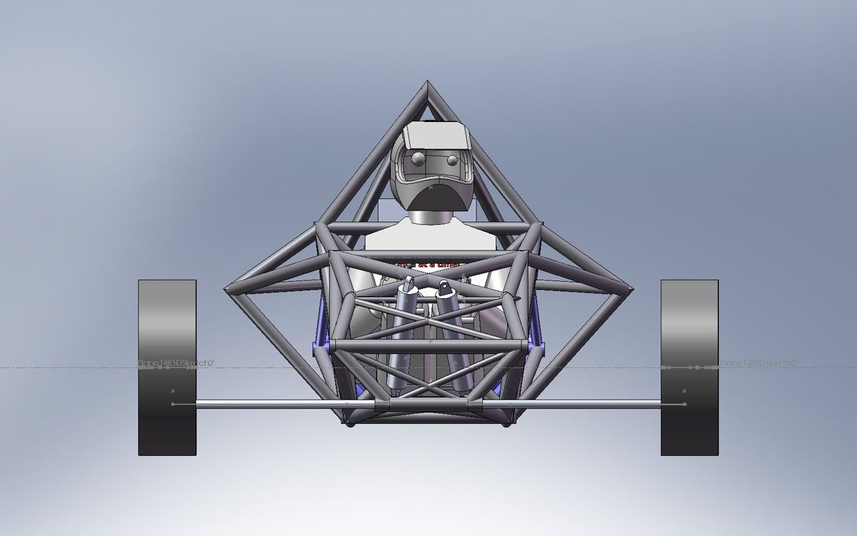
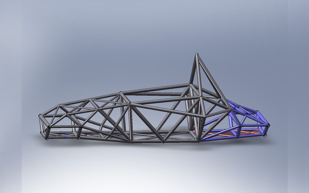
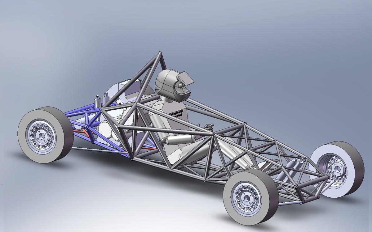
Last thing first. In the rear I added one more tube between the rear suspension and the bulkhead. (nr. 1 in the pic). I also added one tube across the rear triangles that support the roll hoop.

I also placed the roll hoop support tubes to connect at a single point, which should improve stiffness. The roll hoop will still be round, but the supports will meet in the middle.


This raised the stiffness to 7074 Nm/deg and 70.33 kg, which gives me a factor of 100... not bad for a couple of tubes.. :) It could also be a result of bad FEA in the first instance, I suspect there is a lot of stiffnes to be gained from the roll hoop and it probably did not count initially due to the problems FEA has with curved tubing.

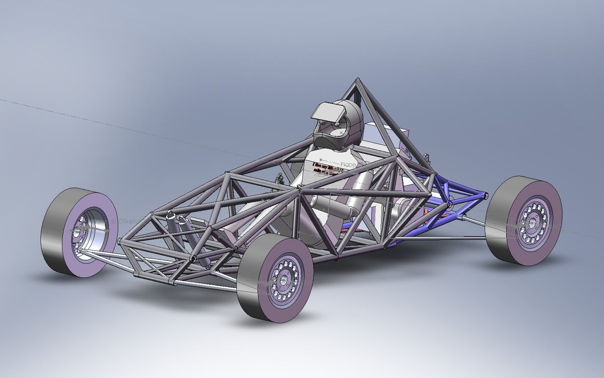
I then checked what can be gained by replacing the side supports of the driver space with a big X.
In my original design I had a big X on the side. This is probably the best, but in my V2 design I went with a different design (nr. 4 in the pic). The reason for this was the fact that when imagining I was changing the gears I would bump my elbow on that tube. So I designed the side tubes differently which gave me more space for the elbows, but also better support for the seat and safety belts.

It was a surprise to find no significant difference, so I staid with my V2 design.


Image


Top
 Profile  
Reply with quote  
 Post subject:
PostPosted: January 12, 2009, 3:23 pm 
Offline
User avatar

Joined: July 22, 2007, 10:58 pm
Posts: 388
Location: Zagreb, Croatia
This left the front part. It was obvious to me that having added length to the chassis, the triangles could not keep the stiffness anymore, mostly because of the shallow angle they formed. So I decided to add some tubing. At the same time, I would use smaller diameter tubing, to keep the weight down.

Here it is, the V2.2
The nose section, between the driver and front suspension is different, more complex with smaller tubing. The rest is the same, with smaller tubing in the rear also, which is now mostly 30x1.5 and 20x1.5 mm.

FEA says 7241 Nm/deg and 69 kg. Factor of 105.2

At the same time, the driver compartment is still the part that flexes the most. I tried playing with the side triangles, but that adds weight but is not as efficient (stiffness wise) as the V2.2 design.

So, now I am in a dilemma. Is 7241 Nm/deg enough for me ? I’d say yes, I could probably use only 5000, but I would really like to know the stiffness of a caterham, westfield or a formula ford. Aiming for only 5000 would mean getting thinner tubing still, but I do not feel comfortable with such a fast car and flimsy tubing... so might just settle for 69 kg and go from there..

On the other hand, V2 with the old nose is simpler build.. :) and not much worse..

If anyone has stiffness info for the caterham / westfiled / formula ford, I am all ears. I know elise is about 10500 Nm/deg...


Image

Image

Image

Image

Image


Top
 Profile  
Reply with quote  
 Post subject:
PostPosted: January 21, 2009, 11:49 am 
Offline
User avatar

Joined: July 22, 2007, 10:58 pm
Posts: 388
Location: Zagreb, Croatia
Used the last week to get some more clamps, I think I will need the m when putting the frame togeather. Additional problem is how to clamp round tubing, so I used my hole saw to make some brackets to hold the tubes..

Image

After figuring out my holesaw notcher will not do for the frame, I redeveloped the solidworks method where by I transform the trimmed tubing drawings from solidworks into self adhesive stencils for the tubes..

Image

More info in the tools section HERE http://www.locostusa.com/forums/viewtopic.php?t=6009


Top
 Profile  
Reply with quote  
 Post subject:
PostPosted: January 21, 2009, 3:16 pm 
Offline
User avatar

Joined: July 6, 2008, 12:48 am
Posts: 653
Location: Amador County, CA
wow... :shock:

_________________
+442 - Miata


Top
 Profile  
Reply with quote  
 Post subject:
PostPosted: January 21, 2009, 9:58 pm 
Offline
User avatar

Joined: August 9, 2007, 2:07 pm
Posts: 302
Location: Downingtown, PA
Maybe I'm missing something but have you checked the clearance in front of the engine for the exhaust? It looks really tight to the frame?


Top
 Profile  
Reply with quote  
 Post subject:
PostPosted: January 21, 2009, 10:30 pm 
Offline
User avatar

Joined: July 22, 2007, 10:58 pm
Posts: 388
Location: Zagreb, Croatia
I did, I had a wooden model first

part of the problem is that the model in the picture is hayabusa model not gsxr1000...... however, I will mount the engine to the central part of the frame before proceeding with the build of the rear part..


Top
 Profile  
Reply with quote  
 Post subject:
PostPosted: January 21, 2009, 10:33 pm 
Offline

Joined: August 15, 2005, 10:13 pm
Posts: 7043
Location: Charleston, WV
That tube miter stencil thingy is genius! Great work! :)


Top
 Profile  
Reply with quote  
PostPosted: February 5, 2009, 10:34 am 
Offline
User avatar

Joined: July 22, 2007, 10:58 pm
Posts: 388
Location: Zagreb, Croatia
really busy at work... luckily my workshop is at work so I use the project to blow off some steam from time to time.. :)
Time to weld something finally..

Unlike the common rule of tacking everything togeather and then welding it, and attaching the suspension pickups at the end.. I am going the other way around.. :)
My suspension pickups will be inside the tubes.. so I am building the car from the center toward the ends.. drivers cell first.. so the suspension sub frames will be welded on last aligned relative to the build table..
also, I have a thing about welds inside the joints.. so I plan on fully welding all the tubes in the joints... which asks for some imagination when welding and paying attention to the sequence in which the tubes will be assembled..

first thing is the top frame around the driver... marked yellow in the pic
Image


Using some rectangural profiles I built a provisional jig on my build table...
Image

Image

this gave me a good base to do the final fitting on the tubes..
Image

Image

before tacking I clamped all the tubes. Tacked one side then turned the frame in the jig to tack the lower part, this gave me the indication on the warping during tacking and prooved that my jig was symmetrical..

Before the final welds I have to refill my argon bottles... I have two, because I want to back purge the welds..

I also drilled two holes on the underside (which will be covered by other tubes) to let the gasses escape and to provide the entry for the back purging argon...
Image

_________________
Building a single seater middy BEC with GSXR 1000 power :)
build log: http://locostusa.com/forums/viewtopic.php?f=36&t=5899

day job: http://smg.photobucket.com/albums/v723/turbolimac/portfolio/


Top
 Profile  
Reply with quote  
PostPosted: February 6, 2009, 4:57 pm 
Hi:

I'd like to see some pics of your back-purging setup. Great work thus far.

--Chris


Top
  
Reply with quote  
PostPosted: February 6, 2009, 5:50 pm 
Offline
User avatar

Joined: July 22, 2007, 10:58 pm
Posts: 388
Location: Zagreb, Croatia
oh, it is simple, just a copper tube going in and some aluminium foil around the tacked joints that are not being welded (to save some gas)... the second hole lets the gasses out.. I have a second argon bottle with a separate regulator for it... not a locost solution but considering the price of the tig setup, worth it.. I will make some pics next week as I will not be in the workshop for a couple of days...

also, the idea is to have all the tubes in the frame (or most of them...) connected internally with small holes.... so that in the end I can pump some argon inside and check for cracks...

I notched some 30 mm holes in the lower frame tubing today, which will be used to make a removable attachment for the rear subframe under the engine.. I was real proud of the setup (the holes had to be aligned with the cuts on the other end of the tube, so that they would end up horizontal in the end..).... so I did it.. and guess what... I missed by 90 deg... ended up being vertical instead of horizontal.. :BH: 
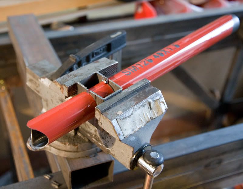
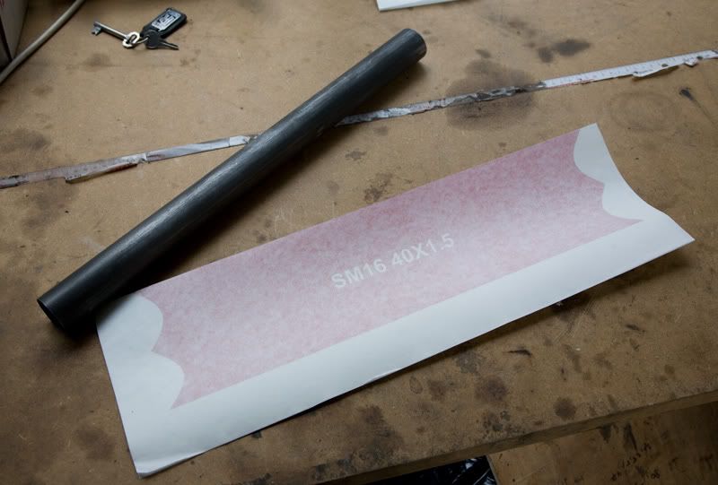
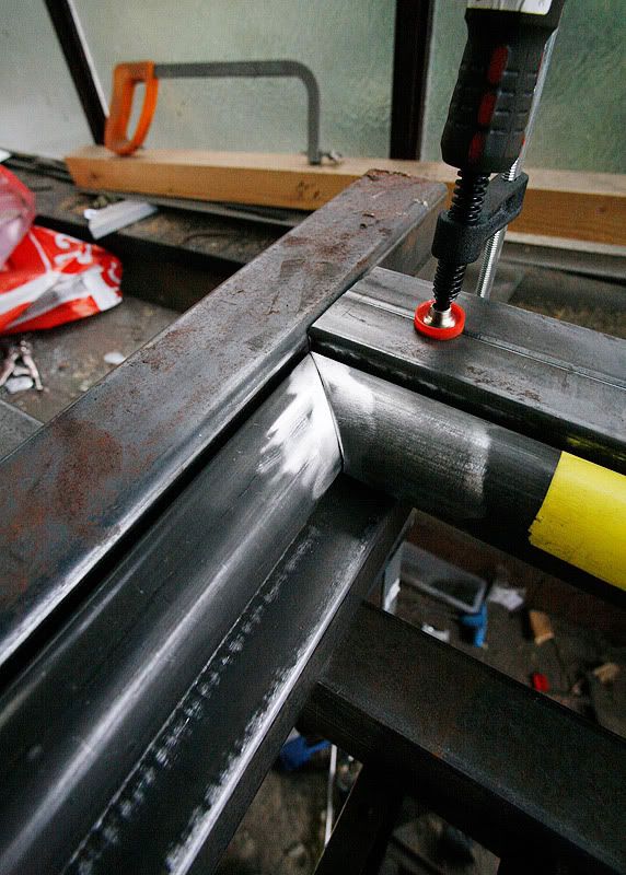
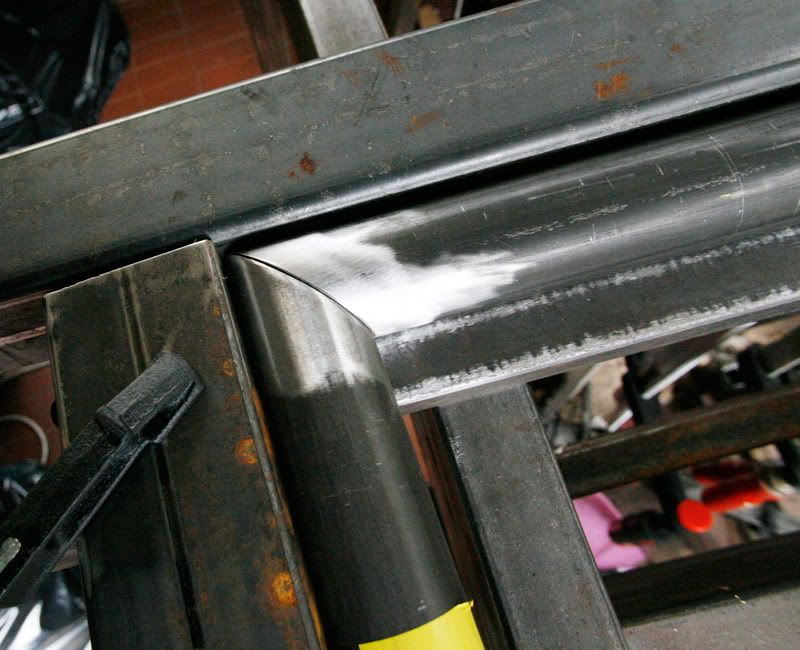
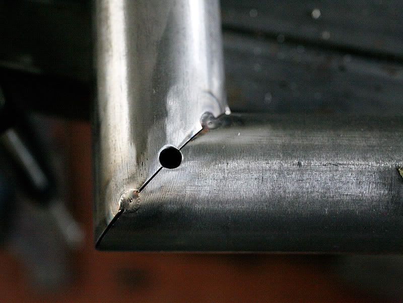
messed up 2 meters of 4130... :)

_________________
Building a single seater middy BEC with GSXR 1000 power :)
build log: http://locostusa.com/forums/viewtopic.php?f=36&t=5899

day job: http://smg.photobucket.com/albums/v723/turbolimac/portfolio/


Top
 Profile  
Reply with quote  
Display posts from previous:  Sort by  
Post new topic Reply to topic  [ 195 posts ]  Go to page Previous  1, 2, 3, 4, 5 ... 13  Next

All times are UTC - 5 hours [ DST ]


Who is online

Users browsing this forum: No registered users and 14 guests


You cannot post new topics in this forum
You cannot reply to topics in this forum
You cannot edit your posts in this forum
You cannot delete your posts in this forum
You cannot post attachments in this forum

Jump to:  
POWERED_BY