LocostUSA.com
http://www.locostusa.com/forums/

sprite into locost
http://www.locostusa.com/forums/viewtopic.php?f=36&t=8564
Page 1 of 36

Author:  vroom [ February 23, 2010, 5:22 pm ]
Post subject:  sprite into locost

I am in the process of turning a rusted out '67 AH Sprite into a locost. Let us leave the question of the wisdom of this in the mists of history. If any of you have tried this you know that a number of the parts don't exactly fit the book frame. So i thought i might whip up something similar but different and possibly less complex.

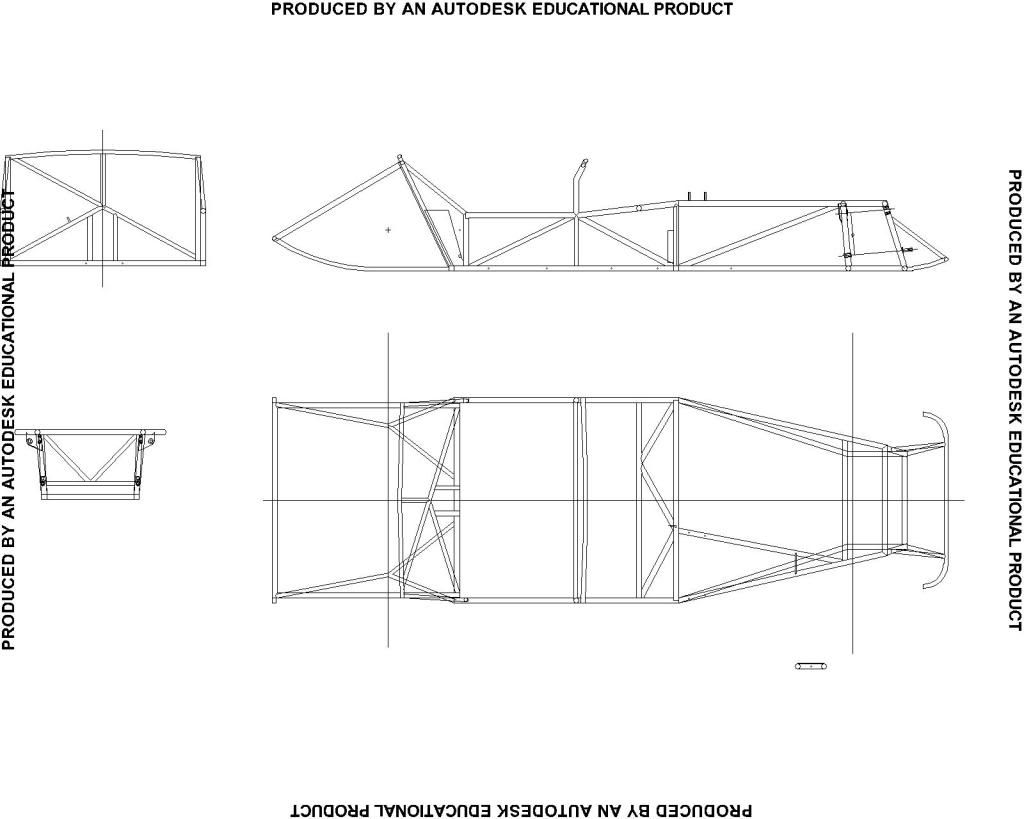
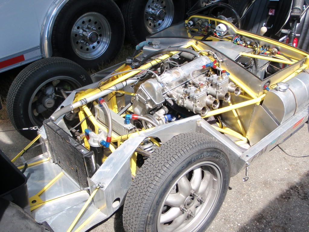
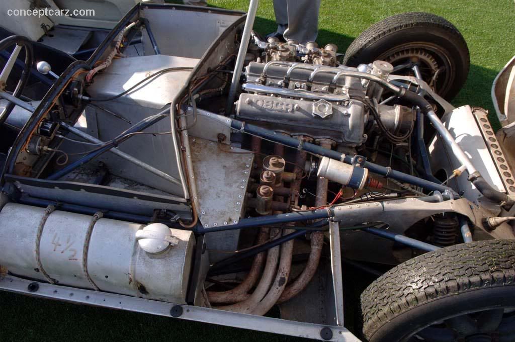
So, I have been working on my cad model and think I have most of the kinks worked out. This led to some reflection and a review of 60s space frames and the books about design of same. Which brought up a new question. That is: why did they divide the engine bay in half and put an added ring of tubes at the front of the footwell??? :shock: :? This struck me as a lot of extra complication in an area that does not have any big loads being taken in and out. On top of that on both the the 7 and 11 Lotuses the top of the frame isn’t triangulated from there all the way back to the back of the cockpit. The only structural reason for this, as I see it, would be to solve a potential Euhler problem with the longish tubes in this area.

Any ideas?

This question has no doubt been dealt with somewhere in this forum but i haven't been able to find it.

Author:  cs3tcr [ February 23, 2010, 8:00 pm ]
Post subject:  Re: sprite into locost

Quote:
That is: why did they divide the engine bay in half and put an added ring of tubes at the front of the footwell???


You've got me confused, can you post a picture of this?

Author:  vroom [ February 23, 2010, 9:20 pm ]
Post subject:  Re: sprite into locost

I'll try. As you can see right behind the engine there is a ring of tubes. You can also see that there is a lot of space in front of and behind the sprite engine. So I could shorten up the wheelbase to match that of the sprite (80"). So the question is why not extend the diagonals back to the bulkhead at the dash board?

I hope this makes some sense.

Author:  firebat45 [ February 23, 2010, 9:44 pm ]
Post subject:  Re: sprite into locost

Call me crazy, but isn't that where your feet are supposed to go? That "ring of tubes" is where the firewall is on a Locost.

Author:  MYTF [ February 23, 2010, 10:12 pm ]
Post subject:  Re: sprite into locost

That appears to be a factory lotus 7 with the small Kent engine. and there is room to move the engine back maybe 4 inches before the bellhousing hits the firewall you can't remove those tubes because you need room for the peddle box. But if your using the original engine from the sprite or other small engine there is room to shorten the wheelbase.

Author:  cs3tcr [ February 23, 2010, 11:09 pm ]
Post subject:  Re: sprite into locost

MYTF,
Thats actually the A-series BMC engine, not a Ford Kent motor.

As for the tubes at the end of the foot boxes, the top tube incorporates the pedal mounts, so i would assume that it would need to stay in place. The lower tube and verticals you might be able to do away with, but then that would leave you with nothing to rivet to when making up the pedal boxes. I remember reading somewhere that when Caterham triangulated the lower engine bay, they found that they could do away with running a continuous tube across the car, which sometimes limits how far back you can push the motor.

On to having the diagonals join the dash board, depending on where you intend to connect them to the dash hoop, it may limit cockpit size. Remember that your knees will be in that general space.

You had mentioned that on the 11's you also didnt understand why they had the tubes in question, well on the Eleven thats where the chassis tapers. So it does have to be in place on that chassis. The early Elevens lacked the tube under the dash, but many had it put in after the fact. Here's a diagram of the Eleven chassis:

Image

Author:  cs3tcr [ February 23, 2010, 11:43 pm ]
Post subject:  Re: sprite into locost

Just remembered i had snapped a pic of a Lola Mk 1 last summer. It has a very unusual firewall layout that you might think about applying to your build:

Image

Author:  vroom [ February 24, 2010, 12:48 am ]
Post subject:  Re: sprite into locost

The Costin and Phipps book has a shot of the Lola series 1 from straight on and it looks like the engine bay diagonal attaches to the dash board cross tube. This is how I got launched down this path in the first place. As can be seen from your photo that isn't true. Although it is close.

My idea was to raise that tube and the side top rails to bottom of the dash height and make the firewall and prop shaft cover from fabricated aluminum. Also i was going to floor mount my pedals.

Author:  cs3tcr [ February 24, 2010, 1:54 am ]
Post subject:  Re: sprite into locost

Here's a shot that i've "borrowed" of a Lola, but from a better angle to see the distance from the firewall 7 point tube junction to the dash:

Image

By the way, you mentioned an 80" wheelbase, for my next project i'm planning on building a car with the same wheelbase, plus a Spridget rear axle. So, i'll be interesting in how you package everything.

Author:  KB58 [ February 24, 2010, 1:56 am ]
Post subject:  Re: sprite into locost

Is that the exhaust directly below the gas tank?... that's how my buddy's Lotus Esprit burned to the ground...

Author:  cs3tcr [ February 24, 2010, 1:59 am ]
Post subject:  Re: sprite into locost

Yup, its below the fuel tank. Funny thing though, the Osca powered car has the exhaust and tank on the opposite side from the Climax powered car. And, all Lotus Elevens other than the two or three with the FPF's have the exhaust under the tanks, my replica included.

Author:  SportsCarDesigner [ February 24, 2010, 9:22 am ]
Post subject:  Re: sprite into locost

Vroom,

The difference, I think, is the arbitrary decision decades ago to keep the upper side rail of Lotus 7 frame rail at toe height rather than at (or raising to) knee height. It gives you a convenient place to land the the 1920s hood and cowl, but it forces the cockpit bay opening (read flaw) to be bigger (longer un-triangulated area) by making you put that "rearmost-front-of-the-cockpit-significant-crossmember" (the not-straight dash hoop is worthless) above your ankles instead of above your knees.

By putting a real cross-member above the steering shaft at the dash, you can triangulate the top plane all the way back to your knuckles. That shortens the open top plane area of the cockpit (from 4 feet to 3 feet in the drawing below).

Attachment:
tall-scuttle_seven.jpg

.

Author:  vroom [ February 24, 2010, 1:54 pm ]
Post subject:  Re: sprite into locost

Part of my reason for asking this question was in hopes someone would have done some FEA on a scheme similar to this. ie long top, bottom and diagonals in the engine bay. The Euhler problem is when tubes are loaded in compression and are too long and thin so they buckle. I was trying to avoid doing the math myself as i don't have any FEA software or expertise and even with a spread sheet it is kind of a drag.

It seems that the generally parallel top and bottom tubes might have as much to do with ease of construction as anything structural.

Author:  Warren Nethercote [ February 24, 2010, 2:29 pm ]
Post subject:  Re: sprite into locost

If it's going to be finished with a Lotus 7 type 'skin' rather than a stand alone Lotus 11 type 'shell', isn't any consideratin of buckling just about moot? The riveted skin prvides lateral stiffness that should elimininate buckling, not to mention the end constraints due to the welded tube intersections of the spaceframe.

Author:  Locost_Johnh [ February 24, 2010, 5:12 pm ]
Post subject:  Re: sprite into locost

Vroom,

By "ring of tubes" you mean the front of the tranny/driveshaft tunnel, right? I modified that area on my car to make room for the whole transmission and most of the bell housing too. I think the Champion book frame was designed with the idea that the tranny is in the tunnel, but the bell housing is out. In a book frame, that is important because making the "ring of tubes" larger means really squished foot wells.

My frame is +4 down the middle and an inch higher at the top frame rails. That gave me the room to enlarge the tunnel mouth and scoot the engine back.

You can see in the photos below a little of what I'm talking about. After the welding was done, one of the last things I did was cut out the section of tube at the bottom of the tunnel mouth. You can see the tranny mount about 18" or so back down the tunnel.

John

Page 1 of 36 All times are UTC - 5 hours [ DST ]
Powered by phpBB® Forum Software © phpBB Group
https://www.phpbb.com/