LocostUSA.com
http://www.locostusa.com/forums/

Tubing: Design Tips
http://www.locostusa.com/forums/viewtopic.php?f=39&t=13617
Page 1 of 1

Author:  Pe7e [ May 2, 2012, 11:41 am ]
Post subject:  Tubing: Design Tips

So, as I was reading myself to sleep with my copy of Construction of Tubular Steel Fuselages (as so many of us do) it occurred to me to share a few of the many good practices the book describes. I've seen a few failures that might have been prevented by reducing stress risers using these techniques. I'd highly recommend the book to any less experienced builder, such as myself, designing or welding their own frame or wishbones. There is good info on weld sequence and direction, gussets, br@ck#ts, etc. I've modeled the details in SolidWorks to avoid reproducing parts of the book.

Attached also are a couple of examples from the Golden Age of motor racing, back in the day when suspensions moved and the driver was the traction control. These are from http://www.britishracecar.com/ a site worthy of support, though a potential time vortex.

The key concept, for me, was to remember that the force vectors on the tubes are parallel the tube axis and to therefore avoid creating stress risers by interrupting them abruptly. i.e. at a right angle. (You do have your "I Will Not Place a Tube in Bending" oath posted in a conspicuous place in the shop, don't you? :) )

Scarf joint, preferred:
Image

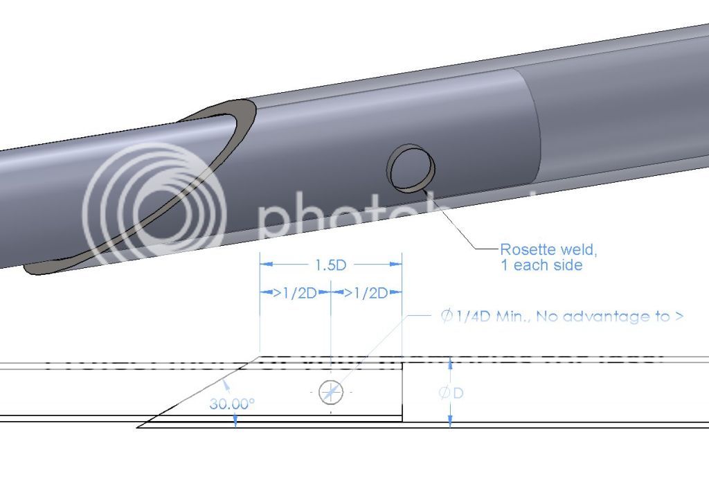
Scarf joint when there is not enough engagement for a long scarf:
Image

Similar concept on a Brabham BT30:
Image

Dent patch or tube reinforcement:
Image

Something similar from a Brabham BT29:
Image


Pete

Author:  horizenjob [ May 2, 2012, 12:03 pm ]
Post subject:  Re: Tubing: Design Tips

Pete, thanks for taking the time to collect the pictures and make the drawings! :cheers:

Author:  GonzoRacer [ May 2, 2012, 12:23 pm ]
Post subject:  Re: Tubing: Design Tips

Hi Pete-
Cool drawings and pictures... Interesting too. Thanks for posting the info! (And for not spelling out that "B" word...)

One question, about the first drawing. In the part which shows dimensions, the upper measurement of the overlapped area shows a dimension of 1.5D, which I assume means 1.5 X pipe Diameter (am I a smart boy, or what!?!?). Just below that, it breaks the same length into two segments and labels them each 1/2D, which I assume is one-half the pipe diameter. Something doesn't add up correctly... It could be a simple typo in the drawing, or am I missing some point here?

I do like their mention of "Rosette welds" on the overlapped pipe segments. That same technique is specified by SCCA for splicing roll cage tubing. It would seem to add a good bit of strength to the joint, and can still be done with normal tools and welding equipment. Good stuff!

:cheers:
JDK

Author:  Pe7e [ May 2, 2012, 1:39 pm ]
Post subject:  Re: Tubing: Design Tips

My pleasure, Marcus. JD, the "carrots" are sort of camouflaged by being right next to the dimension arrows, but the intent was that each of those dimensions be "greater than" 1/2D. In other words there is a bit of leeway in the position of the rosette weld as long as it's not too close to one end or the other. Similarly, the 1/4D hole can be larger, but there is no benefit to "greater than".

By the way, I appreciate both youse* contributions to making this site a good neighborhood. :D


Pete


* "the poetic vernacular of the Sopranos" -Tim Ferriss

Author:  vroom [ May 2, 2012, 2:07 pm ]
Post subject:  Re: Tubing: Design Tips

Great stuff! More tips please!

Author:  cheapracer [ May 4, 2012, 2:54 am ]
Post subject:  Re: Tubing: Design Tips

When I run a tube, nut etc. inside another tube I just simply grab the 4" grinder and quickly cut 2 slots up either side of the tube, saves a lot of nonsense and time.

Page 1 of 1 All times are UTC - 5 hours [ DST ]
Powered by phpBB® Forum Software © phpBB Group
https://www.phpbb.com/