LocostUSA.com

Learning how to build Lotus Seven replicas...together!
It is currently April 18, 2024, 1:48 pm

All times are UTC - 5 hours [ DST ]


Post new topic Reply to topic  [ 74 posts ]  Go to page Previous  1, 2, 3, 4, 5  Next
Author Message
PostPosted: March 23, 2014, 9:52 am 
Offline
User avatar

Joined: February 20, 2009, 2:27 pm
Posts: 531
Location: Reno, Nv
A node is just where two or more chassis members come together in any of the three dimensions.
I think the best way to get your head around the forces on a chassis is make yourself a small model (I made mine of wood) grab it where the suspension attaches and try to twist it. Then work from there to stop the flexing.

_________________
John - Slow and Steady. . . Well slow anyway
Build Loghttp://www.locostusa.com/forums/viewtopic.php?f=35&t=6245


Top
 Profile  
Reply with quote  
PostPosted: March 23, 2014, 9:58 am 
Offline

Joined: January 31, 2008, 5:34 pm
Posts: 781
Location: SW Wes Consin
If you want to find weird nodes look at each welded joint and try to visualize where the tubes, your hands and your weld helmet will have to be to get the joint welded. A good idea (from expierence ) any designer of frames should try. Weird nodes are the ones that cannot be welded. I might add this is why a lot of frames are the way they are.


Top
 Profile  
Reply with quote  
PostPosted: March 23, 2014, 10:02 am 
Offline
User avatar

Joined: June 12, 2012, 8:40 pm
Posts: 472
Location: Mount Airy, NC
Quote:
could some pleas explain NODES to me. if there are weird nodes then how do I go about fixing them

In FEA (Finite Element Analysis) nodes are the end points of the elements. In 2 dimensional elements that would be used for a frame like this, the element would be represented as a straight line with a point (node) at each end. Good design practice is to have the centerlines of your tubes come together at a commen point to make the transfer of loads more efficient. See crummy sketch below:
Attachment:
001.jpg

Sorry for the crude sketch but I'm at home and AutoCAD and the rest of the fancy stuff is at work. My guess at the odd nodes comment is that the rectangular tubes are making the centerlines offset from each other. That offset will cause bending moments in the frame that would not be there if the centerlines came together at a single point. I'm guessing that because you asked for help with frame analysis. Or it could be like vroom said, more of a constuction thing.


You do not have the required permissions to view the files attached to this post.

_________________
My car viewtopic.php?f=37&t=16434
1930s Style Sports Car viewtopic.php?f=36&t=16888


Top
 Profile  
Reply with quote  
PostPosted: March 23, 2014, 4:09 pm 
Offline

Joined: March 7, 2014, 3:47 am
Posts: 30
sweet!!!!!!! thank you all.

So the first pic would make the nodes correct with 1x1 running in to 1x2. What about the second pic with 1x1 running into the side of 1x2 with gusset running 3 inches down 1x1?

I swear I'm getting it I just don't know how to figure this one and maybe one or two others.

thanks again. Harold


You do not have the required permissions to view the files attached to this post.


Top
 Profile  
Reply with quote  
PostPosted: March 26, 2014, 3:16 am 
Offline

Joined: March 7, 2014, 3:47 am
Posts: 30
ok here we go again . so with my new node knowledge I try again. 1x2 base and four link mount the rest is all done in 1x1. added solid motor mounts in apx. location in the engine bay. going to use front and mid mount solid no trans mount.

haven't got all the tubes down the sides of the engine bay but I think you can see where in going. thinking that the 1x2 might deal with the weight of the v8 a little better than the 1x1. may still have to remove the center of tube under trans. br11 in the other book and or tube c in THE book.

3............2..............1..............go

please list any thing you see that may be odd.
I don't count but any thing else is fair game. :thmbsup:

thanks again. harold


You do not have the required permissions to view the files attached to this post.


Top
 Profile  
Reply with quote  
PostPosted: March 26, 2014, 9:35 am 
Offline
User avatar

Joined: February 20, 2009, 2:27 pm
Posts: 531
Location: Reno, Nv
Not being a structural engineer, looks fine to me with a few small points.
As you say the engine bay still needs diagonals for the engine weight and torque. With the rest of the chassis being triangulated you are not getting much benefit from the 1x2 tube as the bending forces are small but may help with the engine torque from imperfect (from space limitations) triangulation.
You do know that you are losing most of the benefit from the 1x2 by using it in the vertical position.

For us non engineers I would recommend you build some small models then support them at the suspension points then load, twist and look and the results.

_________________
John - Slow and Steady. . . Well slow anyway
Build Loghttp://www.locostusa.com/forums/viewtopic.php?f=35&t=6245


Top
 Profile  
Reply with quote  
PostPosted: March 26, 2014, 4:28 pm 
Offline

Joined: March 7, 2014, 3:47 am
Posts: 30
may be I'm thinking of this wrong. the 1x2 vertical should carry the weight of the engine better. not stiffen the chassis much. isn't that correct ?


Top
 Profile  
Reply with quote  
PostPosted: March 26, 2014, 8:50 pm 
Offline
User avatar

Joined: January 2, 2009, 1:45 pm
Posts: 1322
Location: Halifax, Nova Scotia
The idea of a space frame or a truss is that you carry loads and provide stiffness (two different things in many cases) more efficiently than with a single great lump of (insert steel, wood, etc.). The 1x2 members on the bottom of the chassis are the bottom web of the truss or (here) space frame and they will contribute best to bending stiffness if more of their material is located closer to the extreme fibre (the bottom of the frame). To do that, the 1x2s have to be oriented on the flat rather than vertically. Don't think of resisting bending loads in individual members: think of the whole frame resisting bending and it does that better with more material at the extreme fibres.

_________________
Warren
Isuzu Pickup/SR20DE, +401 COLD frame
Build Log: viewtopic.php?f=35&t=11601


Top
 Profile  
Reply with quote  
PostPosted: March 26, 2014, 10:01 pm 
Offline
User avatar

Joined: June 12, 2012, 8:40 pm
Posts: 472
Location: Mount Airy, NC
Quote:
Don't think of resisting bending loads in individual members: think of the whole frame resisting bending and it does that better with more material at the extreme fibres.

Quite right, but the problem here is that the side panel seen in cross section is already bias towards the bottom. Flipping it with the 2" side down will further bias the cross section to the bottom. Since the maximum stress is at the furthest distance from the neutral axis, turning the 1 x 2 over will increase the distance from the neutral and the top tube and raise the stress in the top tube. The top and bottom tubes should be the same cross section to put the neutral axis in the middle, giving the shortest distance to the extreme fibre. But that is just looking at the side panel by itself, the frame taken as a whole is more complicated.

_________________
My car viewtopic.php?f=37&t=16434
1930s Style Sports Car viewtopic.php?f=36&t=16888


Top
 Profile  
Reply with quote  
PostPosted: March 26, 2014, 11:02 pm 
Offline

Joined: March 7, 2014, 3:47 am
Posts: 30
WOW first things first :ack: I'm kind of lost after that last couple post.

In order from first to last from my last post.

1. MYTF thanks for your contributions. I have limited metal tools and NO wood working tools. I under stand what you are saying but wood and me are like fire and water they have a hard time co-existing. I believe you are wright, a model for some one with that skill set or desire it would be a great idea.
Thanks for stating the 1x2 strength conversation this is going to be good!!!!!!!!!!!! p.s. your car is awesome!!!!!!!!!!!!!! blue and orange yah buddy. :cheers:

2. Warren Nethercote and Run87k WOW I'm still looking for the top of my head. found it now if I can just get the rest of it back in there! so if im reading this correctly. the tube on the bottom is making the tube on the top work harder and if I lay it down it will bee even stronger and make the top bar work even harder. if this is the case how do I bring the balance back?

I under stand that just up sizing works. I'm a plus sized guy with an adventurous wife. that means I will need to fit in bolth sides and the +4 frame in mock up still seems tight.

it seem no one has been able to answer my node question or I think I would still be working on the 2x1 vertical bottom and the 2x1 horizontal top rail. which if I'm reading this right would bring balance back to the center of the frame. I think? or would it? here's the pick again just in case some one wants to take a crack at it.


You do not have the required permissions to view the files attached to this post.


Top
 Profile  
Reply with quote  
PostPosted: March 27, 2014, 10:18 am 
Offline
User avatar

Joined: January 2, 2009, 1:45 pm
Posts: 1322
Location: Halifax, Nova Scotia
Harold,

Run is correct: balanced structure top and bottom (in a general sense) helps keep the working stresses balanced on the top and bottom of a beam.

Your tapered filler seems a good way to strengthen the joint between a 1x2 and a 1x1 member. If the 1x2 is longitudinal and the 1x1 is transverse I wonder (i.e. I am not convinced intuitively) if it is even necessary. But it wouldn't hurt.

_________________
Warren
Isuzu Pickup/SR20DE, +401 COLD frame
Build Log: viewtopic.php?f=35&t=11601


Top
 Profile  
Reply with quote  
PostPosted: March 27, 2014, 10:26 am 
Offline
User avatar

Joined: February 20, 2009, 2:27 pm
Posts: 531
Location: Reno, Nv
To build a 1:8 scale model get yourself a hot glue gun about $5, a knife, and some 1/8 inch balsa or poplar from your local hardware store. I used file folder paper for the floor. It should only take a few hours for each one.

_________________
John - Slow and Steady. . . Well slow anyway
Build Loghttp://www.locostusa.com/forums/viewtopic.php?f=35&t=6245


Top
 Profile  
Reply with quote  
PostPosted: March 27, 2014, 2:18 pm 
Offline
The voice of reason
User avatar

Joined: January 10, 2008, 4:47 pm
Posts: 7652
Location: Massachusetts
Harold you are making good progress here and I'm glad you keep coming back and trying because it probably means you can carry off the project. :cheers:

Consider instead of supporting the motor that you are hanging it instead. Ultimately it is hanging because the coil over units connect to the top rail. So that implies that if the car frame is a beam, the upper rail is compressed to carry the motor and the bottom rail is stretched, in the big picture anyway. Members in compression argue for larger section diameter or section.

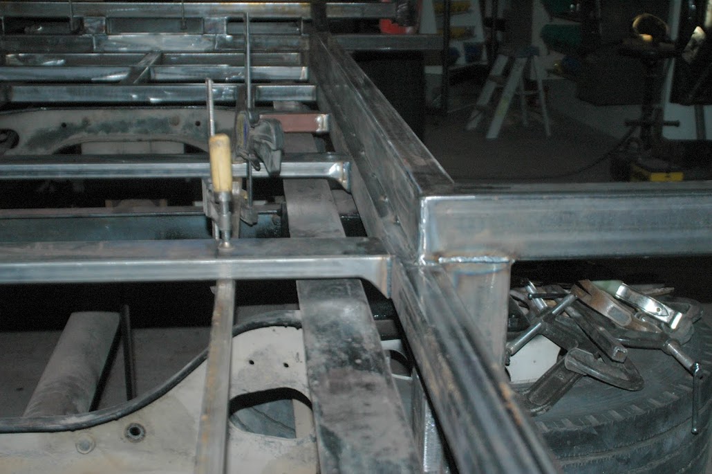
In your frame picture you have not included the diagonals on the side of the engine bay. You would do that later I assume. On the frame design I am working on the engine bay sides have two diagonals that make a downward "V" near the motor mount. So the weight of the engine goes up the diagonals right away and the upper and lower rails carry tension and compression. If you can arrange things that way.

So there is a good argument to make the upper rail bigger, but less so the bottom. If the bottom needs to be bigger to support the engine, it means you aren't getting the weight of the engine into the rest of the frame well ( because you're using a lot of bottom rail to do that job ).

The good thing about getting the weight spread out into the frame is that the loads get lower. A twelve inch tall beam has lower loading to hold this motor than a 2" beam. Getting there is the trick.

So I think moderately larger square section upper rail is the ticket for you. Consider 1.25" square at least.

_________________
Marcus Barrow - Car9 an open design community supported sports car for home builders!
SketchUp collection for LocostUSA: "Dream it, Build it, Drive it!"
Car9 Roadster information - models, drawings, resources etc.


Top
 Profile  
Reply with quote  
PostPosted: March 27, 2014, 2:36 pm 
Offline
User avatar

Joined: July 27, 2013, 3:16 pm
Posts: 336
Location: Cedar City UT
Harold
sorry, that i didnt follow up on my post about strange nodes...
but i see that other members explained it very well :cheers:

yes, your sketch will work to make the transition from different size tubing,
but i highly recommend you to weld the wedges to the cross tube first before you weld them into the frame
this will keep welding "pull" or distortion a lot more tolerable :wink:

btw
i did that same thing on my Truck (with custom air ride cab/sleeper subframe)
Image
i was obsessed with making the subframe riding as low as possible over the truck frame :roll: ,
so i used rectangular tubing and wedges for some of the floor crossmembers to get a little more clearance

_________________
- Stephan - Image


Top
 Profile  
Reply with quote  
PostPosted: March 27, 2014, 11:44 pm 
Offline

Joined: March 7, 2014, 3:47 am
Posts: 30
Thanks again you guys make it so much easier to under stand. :cheers:

so let me recap.

As I get it the top rail of the frame should be 1.25 or 1.5 and then the rest of the frame could be 1x1 and end up with a much stiffer frame then the way it is designed now? Or at least as stiff as it is now.


Top
 Profile  
Reply with quote  
Display posts from previous:  Sort by  
Post new topic Reply to topic  [ 74 posts ]  Go to page Previous  1, 2, 3, 4, 5  Next

All times are UTC - 5 hours [ DST ]


Who is online

Users browsing this forum: No registered users and 14 guests


You cannot post new topics in this forum
You cannot reply to topics in this forum
You cannot edit your posts in this forum
You cannot delete your posts in this forum
You cannot post attachments in this forum

Jump to:  
POWERED_BY