First the proper calculation for the simple couple is M = d * F where d is the distance between the equally opposing forces and F is the force at one application point. Example A spells this out pretty clearly.
http://www.google.com/url?sa=t&rct=j&q= ... WU&cad=rjaF= 2400lbs
d = 2.978ft x 2 = 5.956ft
M= 14,294 lb-ft.
TR = 14,294/7.3 =
1958 lb-ft/degFixing 3 corners and loading 1 can be done but you have no basis to judge from so 4,000ft-lbs/deg for that won't be comparable because most everyone else with those numbers only fixes 2 points of the chassis. Fixing 3 should require higher stiffness values than 4000.
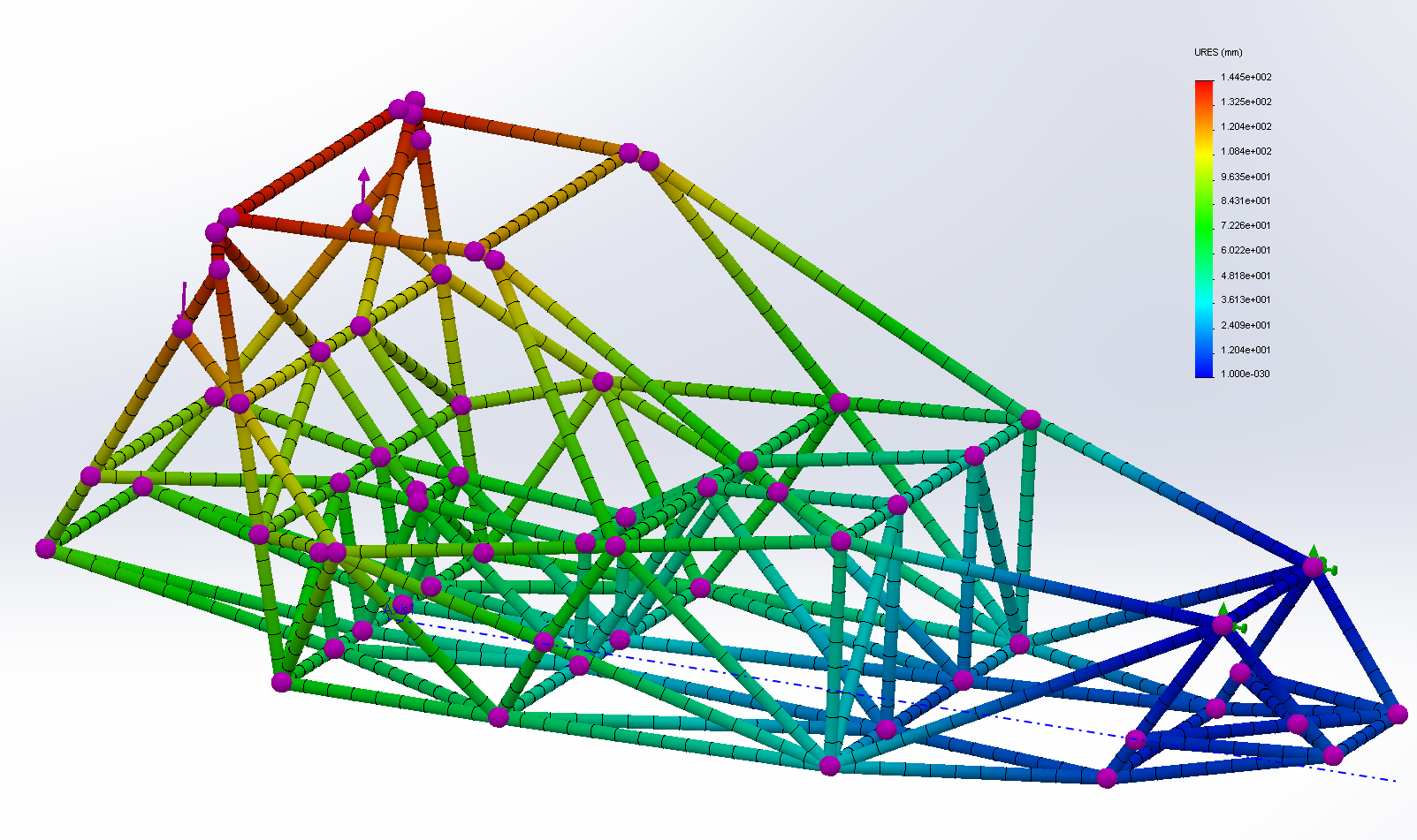
Finally, I don't think you're modeling the test correctly for what you actually care about. 2400lbs is an awfully large input force for an on-track cornering situation and could cause abnormally large deflections in the software that aren't real. If you are trying to find out how stiff your chassis is on a race track as opposed to some dangerous situation I would bring that number down to something more realistic which you should be able to calculate starting off with a 1.0G cornering load. As an example, I gradually increased load from 25lbs to 125lbs on each side of my FSAE chassis. We used measuring tubes that stuck out 24in. from centerline at specific points along the chassis for very fine measurements of deflection. You can see the real world example in the attached pic but in the model you can easily just output the node displacements of the dummy tubes.
Our chassis was pretty stiff for a tube chassis without any stressed panels with maximum angular displacements of less than 0.5 deg in all situations. 2000ft-lbs/deg sounds like a decent start but it means nothing because 7.3 deg of angular deflection is extraordinary which may just be a byproduct of your high input forces.