LocostUSA.com
http://www.locostusa.com/forums/

Locost 4 link solution ....
http://www.locostusa.com/forums/viewtopic.php?f=5&t=13741
Page 1 of 3

Author:  cheapracer [ June 8, 2012, 6:04 am ]
Post subject:  Locost 4 link solution ....

Another "Bex Solution" by cheapracer, because Bex is Better!

4 links trailing arms should not be parallel!! .... even though 99% of the mod car population thinks that it goes without saying they should be.

Trailing arms do not roll around a center point between them, nor do they rise in a 2 dimensional plane in roll, they roll 3 dimensionally controlled by points (RC and chassis pivot) some distance away, there's 2 sides of them and they are at different points of that arc hence their longitudinal chord lengths change at different rates. This is pyhsics that can't be changed regardless that your brain is now screaming "Trailing links should be parallel!!".

Why do links bind? Because they immediately become non-parallel (longitudinally) at the first instance of roll and the change in the link's chord lengths opposes the opposite side's trailing links that are also trying to do their thing causing bind.. specifically the top link in bump shortens faster than the opposite side's top link in droop and the axle won't twist to compensate.

Image

By having non-parallel links we have one side's top link chord length shorten in roll (bump) while the opposite side's top link shortens at closer to the same rate while in droop.
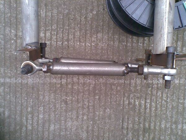
The test setup;

For a practical sample I chose the very popular Locost 4 link rear trailing link setup as per the book specifications. Although using some scrap steel, great care was taken in dimensional accuracy. Note horizontal heims were used on the dummy "axle" upper pivots to enable quick height adjustment for the test ..
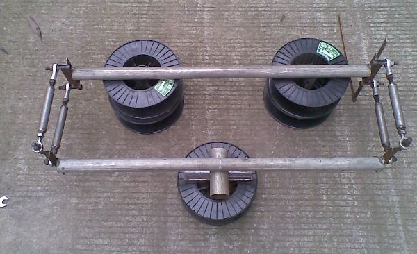
Image

Links and jig;
Links were 292mm in length as per book, initially 140mm vertical spread and all 4 jigged for accurate length ..

Image

The result;
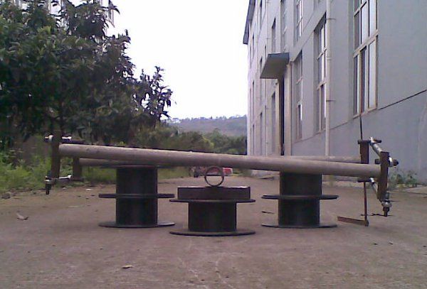
With the links parallel as per the book specs and common mythology that 4 links should be parallel(not to mention 99% practical application), bind was quickly established at around 6 degrees. Axle had to be mildly forced to this limit, would not fall under it's own weight after about 4 degrees and binding was felt well before limit. Note at this point all 4 links were very tight to swivel due to the binding and had not reached their travel limit ....

Image

With the links set non-parallel (rear pivots set 8mm closer together), bind was non-existent, the axle fell under it's own weight until travel limit of horizontal heims was reached. note that the only reason the axle stopped at this point was because the horizontal heims ran out of travel - THE AXLE WOULD HAVE TRAVELED MUCH FURTHER FREELY with vertical heims. The lower links swivelled freely and easily indicating little bind. Stupid picture should read "255mm" on the left..

Image


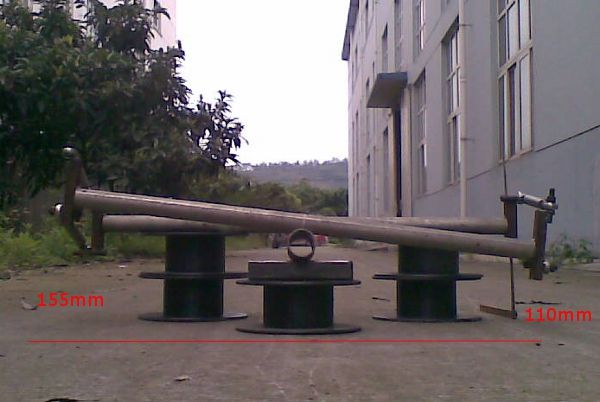
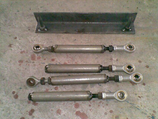
The resulting "winning" dimensions that you might use on your Locost, note the horizontal hiems have run out of travel ....

Image

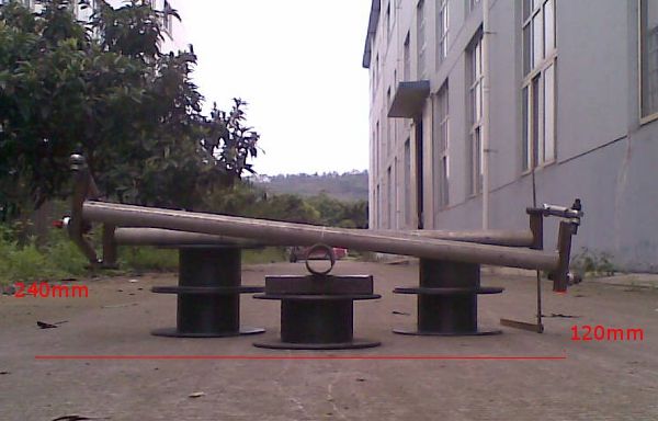
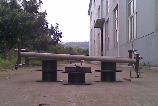
I also tested upside down with the RC centered to a live axle (above test with RC 50mm below wheel centerline) with similar results... note in the lower picture the trailing arms have reached horizontal having traveled further and again i stress that it only stopped there because the horizontal hiems ran out of travel, not because of bind!

Image
Image

I take these tests very seriously and was very careful to check and recheck before taking results.


Should you do it even though theres thousands of Locost's running around today successfully? Well that's entirely up to you now you have the information, note that the serious binding starts near the end of suspension travel limits on a typical Locost but it is there. At maximum bump this will tend to creat oversteer due to the binding creating anti-roll besides the higher wear/stress on your heims and chassis mount stress. Of course rubber bushings masks this (but doesn't remove the binding anti-roll) but that's not good enough for me and it shouldn't be for you.

On a Locost this should be very easy to check/modify for yourself by merely adding 2 extra holes on the rear axle brackets as shown (can weld a washer over later) or raise the front mounts the same amount. Note that at 120mm test seperation binding had seriously returned, 132mm was the sweet spot (no need to take that too literally, 130mm is also fine);

Image

As another proof of point, I currently have a mock up of another 4 link (DeDion) with 710mm long non-parallel trailing arms with vertical seperation of the pivots at 310mm front and 290mm rear - a full 20mm difference. With the trailing arms parallel I get serious bind within 100mm of travel but with the rear pivots 20mm closer I can lift either side a full 200mm freely using 1 finger and only limited by chassis interference in this case. Pictures another day, phone battery dead.

Don't believe me? Make up your own test rig, use some wood, nails and hook screws or try this on your current 4 link, it's not that difficult to prove or understand once "you see it"!

Some people will not be convinced because of the mindset about what 4 links should be ie; "Parallel!!" but a few of you more flexible thinking might benefit from this for your builds ;-)

Author:  GonzoRacer [ June 8, 2012, 7:59 am ]
Post subject:  Re: Locost 4 link solution ....

Yo Cheapracer-
Good write-up, thanks!
:cheers:
JDK

Author:  JackMcCornack [ June 8, 2012, 10:01 am ]
Post subject:  Re: Locost 4 link solution ....

Well dang! Cheapracer, thank you for going to the trouble to do that. Verrry interesting, as they used to say on Laugh-In.

I'm going to ask you because you've got a jig set up already...excuse me for laying more work on you, and only do this if it's something you think is worth checking...when there's a panhard bar in the mix I think it throws a Spaniard in the works. If the left wheel is the high wheel, then the left trailing arms have the upper trailing arm axle attachment point moving left and the lower trailing arm attachment point moving right, so if the axle itself moves right (as it does in the typical Locost with panard attached to the left side of the rear axle), the upper arm "shortens" faster than the lower arm, which I'd think would cause a bind. If you let the axle move freely from side-to-side (even a small amount, possibly too small to see) the bind is relieved by the axle seeking its own lateral location. Could you add a panard bar to your rig and see what effect it has?

I'd do it myself but I'm three days away from my welder and have some parts to ship when I get back to the shop.

I've often thought a single rubber bushing on the chassis end of one trailing arm would be a good idea. But as noted by others, Locosts (and lots of hot rods) seem to have enough chassis flexibility to get by.

Cheapracer, that was an excellent demonstration. A picture is worth a thousand words, and a photo is worth a thousand pictures.

I suspect I've never felt that bind because I've always worked with entire axle assemblies (come to think of it, axle and wheel and tire assemblies, because I've also been checking out body fit when I've done my range-of-motion tests) and the heavy axle does disguise light binding.

PS--I googled the heck out of "Bex" and learned little besides it rhymes with sex. What is Bex? Or what are Bex, if Bex is the plural.

Author:  cheapracer [ June 8, 2012, 10:53 am ]
Post subject:  Re: Locost 4 link solution ....

JackMcCornack wrote:
Well dang! Cheapracer, thank you for going to the trouble to do that. Verrry interesting, as they used to say on Laugh-In.

Could you add a panard bar to your rig and see what effect it has?


Cheapracer, that was an excellent demonstration. A picture is worth a thousand words, and a photo is worth a thousand pictures.


PS--I googled the heck out of "Bex" and learned little besides it rhymes with sex. What is Bex? Or what are Bex, if Bex is the plural.


I had 2 motivations for doing it and believe it or not one was because you guys are all pretty decent and I thought it may be of interest.

I probably can add a Panhard over the next few days, see how I go.

Pictures help but man, you just can't convey feel and there's a big difference between the 2.

"Bex" is the short nick for my surname, it might surprise some to learn that Dad didn't name me Cheapy although for a while I did think my name was "Nick Off Will Ya" :wink:

Author:  horizenjob [ June 8, 2012, 11:46 am ]
Post subject:  Re: Locost 4 link solution ....

Thanks for the effort, there's nothing like some simple lab results!

I suppose this is why oval track racers use bearings in their axle mounts and float the axle housing. Then they can move the links all over the place for all those other reasons they come up with.

Author:  cheapracer [ June 8, 2012, 12:07 pm ]
Post subject:  Re: Locost 4 link solution ....

Oops.

Author:  Posthumane [ June 8, 2012, 12:13 pm ]
Post subject:  Re: Locost 4 link solution ....

Thanks for the great addendum to yesterday's discussion Bex. :cheers:
I don't think the panhard rod will change the outcome much. With the panhard rod being mounted on the left side of the chassis, and horizontal at the nominal ride height, the axle will tend to move left slightly with a bounce or droop on the right side. The effect is small, about 1.2mm for a 50mm bump with a 1016mm (40") panhard. In a pure left wheel bump it will move right an even smaller amount due to the axle pivot being below the axle.

Author:  cheapracer [ June 8, 2012, 12:22 pm ]
Post subject:  Re: Locost 4 link solution ....

JackMcCornack wrote:
Could you add a panard bar to your rig and see what effect it has?


By the way, I presume you want as horizontal as possible but what RC height did you want (reletive to the wheel centerline)?

Posthumane wrote:
Thanks .. Bex.


Cheapy ;-)

Author:  a.moore [ June 8, 2012, 2:03 pm ]
Post subject:  Re: Locost 4 link solution ....

Interesting experiment. How sensitive was the location of the holes to binding? If you moved a hole lets say 1/16" would it be enough to cause or eliminate binding?

I always though the rear suspension from an earlier Seven was a good compromise since it did not over constrain the rear axle (allegedly it was notorious for breaking light weight axles of the day though.) I'm sure the binding is also at least partially to blame for the failed trailing arm chassis brackets.

Its probably worth noting that having the links non-parallel will also create some amount of anti-squat.

Author:  gregaustex [ June 8, 2012, 2:29 pm ]
Post subject:  Re: Locost 4 link solution ....

thanks for the education . I love this forum.

Author:  cheapracer [ June 8, 2012, 2:49 pm ]
Post subject:  Re: Locost 4 link solution ....

a.moore wrote:
How sensitive was the location of the holes to binding? If you moved a hole lets say 1/16" would it be enough to cause or eliminate binding?


By holes do you mean the heim joint/bushing bolt holes? By 1/16 do you mean the distance an average home workshop might be off by? If the builder was that bad and say 4 to 6 of the 8 holes were out then yes, there would be a noticable difference either way but if the workmanship was that bad then I would be concerned about the entire car!

a.moore wrote:
Its probably worth noting that having the links non-parallel will also create some amount of anti-squat.


(From the standard mounting position) I doubt you would notice it. Anyway, you are refering to just dropping the rear upper hole whereas you could also split the difference or raise the lower hole.


a.moore wrote:
I'm sure the binding is also at least partially to blame for the failed trailing arm chassis brackets.


Agreed. seen a number of older rally cars tearing out the brackets as well, tell them why and the answer is the same, ie: Parallel! :wink:

a.moore wrote:
Interesting experiment.


I already knew what the result would be (but not the specific Locost details) but now's the time for me to gear up and give people confidence in systems that I will be peddling, that's the 2nd reason for all this recent activity.


Damn, they cut this advert off just as he is about to say "Bex is better!".

http://www.youtube.com/watch?v=BF6ffbz70SY

Yay, found one, at 16 second mark ...

http://www.youtube.com/watch?v=q0rsiC-C8hs

Author:  NoahKatz [ June 8, 2012, 4:29 pm ]
Post subject:  Re: Locost 4 link solution ....

The root problem is that four links overconstrain a solid axle in torsion.

A symmetric arrangement that isn't would be two lower or upper ones, and an upper or lower one in the middle.

Author:  KB58 [ June 8, 2012, 4:56 pm ]
Post subject:  Re: Locost 4 link solution ....

The issue is due to not having all four links exactly the same length (or the top and bottom pairs exactly the same length.) What happens in a turn is that when one side of the suspension gets compressed, because the links aren't exactly the same length, the arms attempt to rotate the axle tube. At the same time on the other side of the car, that suspension is attempting to move into droop. There, because the links also aren't the same lengths, they may very well try to rotate the axle tube the opposite direction. In effect, the setup can result in the arms attempting to use the axle tube as a very thick antiroll bar. Using rubber bushings in at least two of the links sidesteps the issue.

My brother's old Mazda had a modified four-bar link setup and because of the above, you could jack up one rear wheel only about 1" before the other tire would come up off the ground, too... So much for freedom of motion. Caused all sorts of entertaining handling issues, much like the car had a huge rear antiroll bar, which it in effect, had.

Author:  Miatav8,MstrASE,A&P,F [ June 8, 2012, 6:01 pm ]
Post subject:  Re: Locost 4 link solution ....

:?: :?: :?: You must be joking!

HA! Gotta love a little payback! :P

Just kidding. Shake it off. Don't want to hurt anybodys feelings!

Apology accepted by the way, even if you happen to be wrong.

I have not put a straight axle in anything, and have not given it much or enough thought so I'm sitting this one out. Gotta finish my barn now. :wink:

Author:  horizenjob [ June 8, 2012, 6:16 pm ]
Post subject:  Re: Locost 4 link solution ....

Quote:
Its probably worth noting that having the links non-parallel will also create some amount of anti-squat.


Quote:
Anyway, you are refering to just dropping the rear upper hole whereas you could also split the difference or raise the lower hole.


There will be anti-squat or pro-squat whenever the axle is not traveling perfectly vertically. So this happens already as soon as it starts to move up or down. It really is just a matter of the vertical path the axle takes, not where the holes are.

Page 1 of 3 All times are UTC - 5 hours [ DST ]
Powered by phpBB® Forum Software © phpBB Group
https://www.phpbb.com/