LocostUSA.com

Learning how to build Lotus Seven replicas...together!
It is currently April 28, 2024, 12:22 am

All times are UTC - 5 hours [ DST ]


Post new topic Reply to topic  [ 33 posts ]  Go to page Previous  1, 2, 3  Next
Author Message
 Post subject:
PostPosted: January 18, 2006, 11:28 pm 
Offline

Joined: August 15, 2005, 10:13 pm
Posts: 7043
Location: Charleston, WV
Very nice! what guidelines did you use to establish your setup?


Top
 Profile  
Reply with quote  
 Post subject:
PostPosted: January 18, 2006, 11:34 pm 
Looks nice, and welcome to the board. Do you have any dimensions for the linkage, or did you wing-it?


Top
  
Reply with quote  
 Post subject:
PostPosted: January 18, 2006, 11:40 pm 
Yup when I redo my steering rack mounts I am copying yours too.


Top
  
Reply with quote  
 Post subject:
PostPosted: January 19, 2006, 12:07 am 
Offline
User avatar

Joined: January 18, 2006, 10:41 pm
Posts: 349
Location: Concord, NC
Thanks guys. I'll be happy to share what I have. I'll work on a detailed drawing of my setup and post it. I did actually draw it up in CAD before I made it...but is has been a while.

From what little info I had at the time, this is what I thought was important in the design. I think that one key is symetry about the centerline of the whole system. In the "static" position all three points along the bottom are horizontal to each other. The angles formed between the various pickup points and the center of each belcrank need to be the same from side to side. To establish the roll center, it is a combination of the height of the belcrank system and the angle formed by the two long rods that go to the axle.

It is real easy to find the roll center of the Mumford linkage. It is where the two long outer rods would intersect in space under the belcrank system.

I will get working on that diagram...

_________________
-Jeff

Project Seven
Instagram: @RexRacer19


Top
 Profile  
Reply with quote  
 Post subject:
PostPosted: January 19, 2006, 12:27 am 
Offline
Locostering Information Liaison
User avatar

Joined: August 17, 2005, 1:30 am
Posts: 2397
Location: So CALIFORNIA
Sorry but I got a couple questions about terms I dont understand....Can you clarify?

Quote:
They put a mumford linkage in that car and ran it with an open diff.

What is an Open Diff?

Quote:
He had no wheel spin, even with the open diff

Not sure what this means.....spinning his tires or losing traction (sliding).

Sorry I am having a blonde day.....

_________________
I'll keep an eye out for you!

To err is human...
I am more human than most.


Top
 Profile  
Reply with quote  
 Post subject:
PostPosted: January 19, 2006, 12:35 am 
Wow Jeff, you've got a really good looking car starting to come together. I too plan on going w/ the Mustang II spindles - what lower ball joint did you use on the redesigned arms? Did you think about using a pushrod type suspension in front similar to the Caterham CSR you have pictured for inspiration? Are you building a 'book' frame, or is it closer to a +442? Are you using the Mazda axle unmodified (not narrowed)? I wouldn't mind getting a copy of any plans/drawings you've done for the car, I think it might be good inspiration for mine.

Sorry for so many questions - I'm an 'inquisitive idiot' :lol:

--JOsh


Top
  
Reply with quote  
 Post subject:
PostPosted: January 19, 2006, 12:39 am 
mr.peabody.d wrote:
Sorry but I got a couple questions about terms I dont understand....Can you clarify?

Quote:
They put a mumford linkage in that car and ran it with an open diff.

What is an Open Diff?

Quote:
He had no wheel spin, even with the open diff

Not sure what this means.....spinning his tires or losing traction (sliding).

Sorry I am having a blonde day.....


By open diff, I'm sure he means that it doesn't have a posi-trac unit, or a locked differential unit in there, tieing the two axles together.

As for the wheel spin comment, usually, open diff's will cause one wheel to spin when under heavy accelleration, thereby breaking traction - usually affectionately called the 'one-wheel peel'. Most front wheel drive cars fall under this phenomenon.

--JOsh


Top
  
Reply with quote  
 Post subject:
PostPosted: January 19, 2006, 12:45 am 
Offline
User avatar

Joined: January 18, 2006, 10:41 pm
Posts: 349
Location: Concord, NC
Mr.peabody - by open diff(erential) I mean that it does not have a limited slip and therefore will easily spin the unloaded tire. The mumford linkage helps to keep the "weight" on the tires (from the low roll center) and makes it easier to keep traction while accelerating out of the turns. In turn it is not quite as big of a deal to have an open diff.

OK - Here is a drawing with dimensions of my exact linkage. I don't claim it to be the ultimate, but it does seem to work as designed, and nobody else is putting up any drawings of these things... :wink: :D

Image

_________________
-Jeff

Project Seven
Instagram: @RexRacer19


Last edited by Anonymous on January 19, 2006, 1:04 am, edited 1 time in total.

Top
 Profile  
Reply with quote  
 Post subject:
PostPosted: January 19, 2006, 12:59 am 
Offline
User avatar

Joined: January 18, 2006, 10:41 pm
Posts: 349
Location: Concord, NC
CR_Turboguy wrote:
I too plan on going w/ the Mustang II spindles - what lower ball joint did you use on the redesigned arms? Did you think about using a pushrod type suspension in front similar to the Caterham CSR you have pictured for inspiration? Are you building a 'book' frame, or is it closer to a +442? Are you using the Mazda axle unmodified (not narrowed)? I wouldn't mind getting a copy of any plans/drawings you've done for the car, I think it might be good inspiration for mine.

Sorry for so many questions - I'm an 'inquisitive idiot' :lol:

--JOsh


Hey JOsh,

Many of the stock car places have a screw in type ball joint that is made for the pinto spindle. You can get the threaded ring that it screws into as well. No fancy pushrod systems on this car...just a Keep It Simple Stupid approach on this build. It is meant to be a learning tool about a lot of things, but at the same time, not too many things.

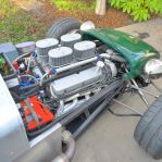
The rear is an unmodified RX-7 unit. Disk brake posi unit from an '84 GSL. The frame is basically a "book" frame with the footwell switched for 'merican left hand drive. I have made a few strength and asthetic mods (with more to come). Nothing really documented in drawings. My lower control arm is in drawing form. If you plan on a book frame, and an RX-7 axle, it would be helpful. When I started this car, I only had Autocad and just made drawings and templates for a few things.

I have been at this thing since the end of 2001. There have been a lot of distractions along the way to keep me from it. With most of that behind, I am hoping that this is the year...

_________________
-Jeff

Project Seven
Instagram: @RexRacer19


Top
 Profile  
Reply with quote  
 Post subject:
PostPosted: January 19, 2006, 2:26 am 
Offline
Locostering Information Liaison
User avatar

Joined: August 17, 2005, 1:30 am
Posts: 2397
Location: So CALIFORNIA
Very Interesting

I am using Mustang II front suspension with screw-in ball joints a "open diff" ( thanks guys) with a live axel, Mazda Duratec and stock 5 speed trans.

I like the K-I-S-S method and I like your approach.... look forward to your future posts.

Welcome aboard R1 Seven

I will have to re-evaulate the panrod vs munford idea before I switch (sounds like it would be better if it performs as suggested)...of course there is plently of time to do that still.
Thanks again

_________________
I'll keep an eye out for you!

To err is human...
I am more human than most.


Top
 Profile  
Reply with quote  
 Post subject:
PostPosted: February 1, 2006, 1:45 am 
Offline
Locostering Information Liaison
User avatar

Joined: August 17, 2005, 1:30 am
Posts: 2397
Location: So CALIFORNIA
http://www.locostbuilders.co.uk/viewthr ... ?tid=32679

_________________
I'll keep an eye out for you!

To err is human...
I am more human than most.


Top
 Profile  
Reply with quote  
 Post subject:
PostPosted: September 24, 2007, 3:24 am 
Offline
User avatar

Joined: January 7, 2007, 3:24 pm
Posts: 682
Location: Visalia, Ca
YouTube mumford video.
http://www.youtube.com/watch?v=jIiEV0DILBw

Rod

_________________
Driving a +442E with 450 Hp Ford 347 v8, T5, 8 stack EFI w/EDIS8 & MegaSquirt ITB Mode.
12,000+ enthusiastic miles as of 1/1/11
http://www.youtube.com/watch?v=jqvYJlYc4GU
http://s124.photobucket.com/albums/p3/beergodrod/
Now building a 1953 Chevy 1 ton panel with Frito Lay truck parts and a Cummins 4BTA
and a 1963 Nova SS


Top
 Profile  
Reply with quote  
 Post subject:
PostPosted: September 24, 2007, 9:08 am 
Offline
Mid-Engined Maniac

Joined: April 23, 2006, 8:26 pm
Posts: 6421
Location: SoCal
I made a cardboard model, using pushpins for pivots. It's invaluable for teaching yourself what's going on. It works the same why that a front A-arm suspension has a "virtual length" greater than the physical parts.

_________________
Midlana book: Build this mid-engine Locost!, http://midlana.com/stuff/book/
Kimini book: Designing mid-engine cars using FWD drivetrains
Both available from https://www.lulu.com/


Top
 Profile  
Reply with quote  
 Post subject:
PostPosted: October 21, 2008, 2:43 pm 
Offline
User avatar

Joined: September 25, 2008, 6:13 pm
Posts: 468
Location: Los Angeles, CA
I am pulling this up from the dead to add some very useful diagrams that I have found on the mumford link.

http://texaslocost.homestead.com/Mumforddrawing.html
this shows one Locoster's solution.

The attached file actually shows you how to design a mumfordlink for your application and desired roll center. I cannot take credit for the drawing, it is not mine.


You do not have the required permissions to view the files attached to this post.


Top
 Profile  
Reply with quote  
 Post subject: Re: Mumford Linkage
PostPosted: December 22, 2023, 1:03 pm 
Offline

Joined: February 8, 2014, 10:47 pm
Posts: 781
Location: Cornelius OR
The problem with panhard's is that it does not work the same for turns in the opposite direction.

A Mumford or a Watts will have the same performance in right or left turn
Both Mumford and a Watts link work the same on the car, with the Mumford being only slightly more complex with the addition of a lever and link.

The main difference between the two is a Mumford can have a much lower roll center than a Watts.
A Mumford can actually have a roll center that is below the pavement!

I'm not sure, but I think the only con of a Mumford would be that the links are shorter.
This may make the Mumford have a shorter sweet spot in suspension travel terms.

I realize this is an old post I am responding to but these details are absent from the topic.
I'm gathering data.

I don't want to band-aid a balance issue messing will shock and spring rates, when a simple roll center adjustment will do.
This goes to stability and driver confidence.
Perhaps most Locost designs do not normally need a lower roll center than a Watts can provide?
And those that cant tell the difference simply install a panhard.

Discuss?

_________________
Honey anyone?


Top
 Profile  
Reply with quote  
Display posts from previous:  Sort by  
Post new topic Reply to topic  [ 33 posts ]  Go to page Previous  1, 2, 3  Next

All times are UTC - 5 hours [ DST ]


Who is online

Users browsing this forum: tibimakai and 5 guests


You cannot post new topics in this forum
You cannot reply to topics in this forum
You cannot edit your posts in this forum
You cannot delete your posts in this forum
You cannot post attachments in this forum

Jump to:  
POWERED_BY