Catching up on threads in this great new-to-me forum…
Section 8 wrote:
With 3 dimensions in a space frame modeling with single elements isn't the best way because the added dimension brings twisting moments that put combined loads into the member. no longer is it just tension and compression it is torsion, shear with the tension and compression.
That’s how the tubes are actually loaded, so I’d stay with the ever so simpler beam elements.
And if it’s really a space frame the torsional stresses in the tubes will be small, as they will be borne by the frame at large.
a.moore wrote:
You're getting there but keep in mind you aren't getting a torsional reading with that number. By applying the load to only one corner, you are getting a combined torsional and beaming stiffness. Keep in mind the torsional rigidity number is to measure the stiffness of the "torsional spring" connecting the front and rear suspensions so you have to twist (not bend) the chassis.
I doubt it would make much difference, since applying pure torsion also applies beaming loads to the opposing faces.
I think of beaming as a subset of torsion, since there’s no way a structure could have torsional stiffness w/o also having beam stiffness, whereas the opposite is not so.
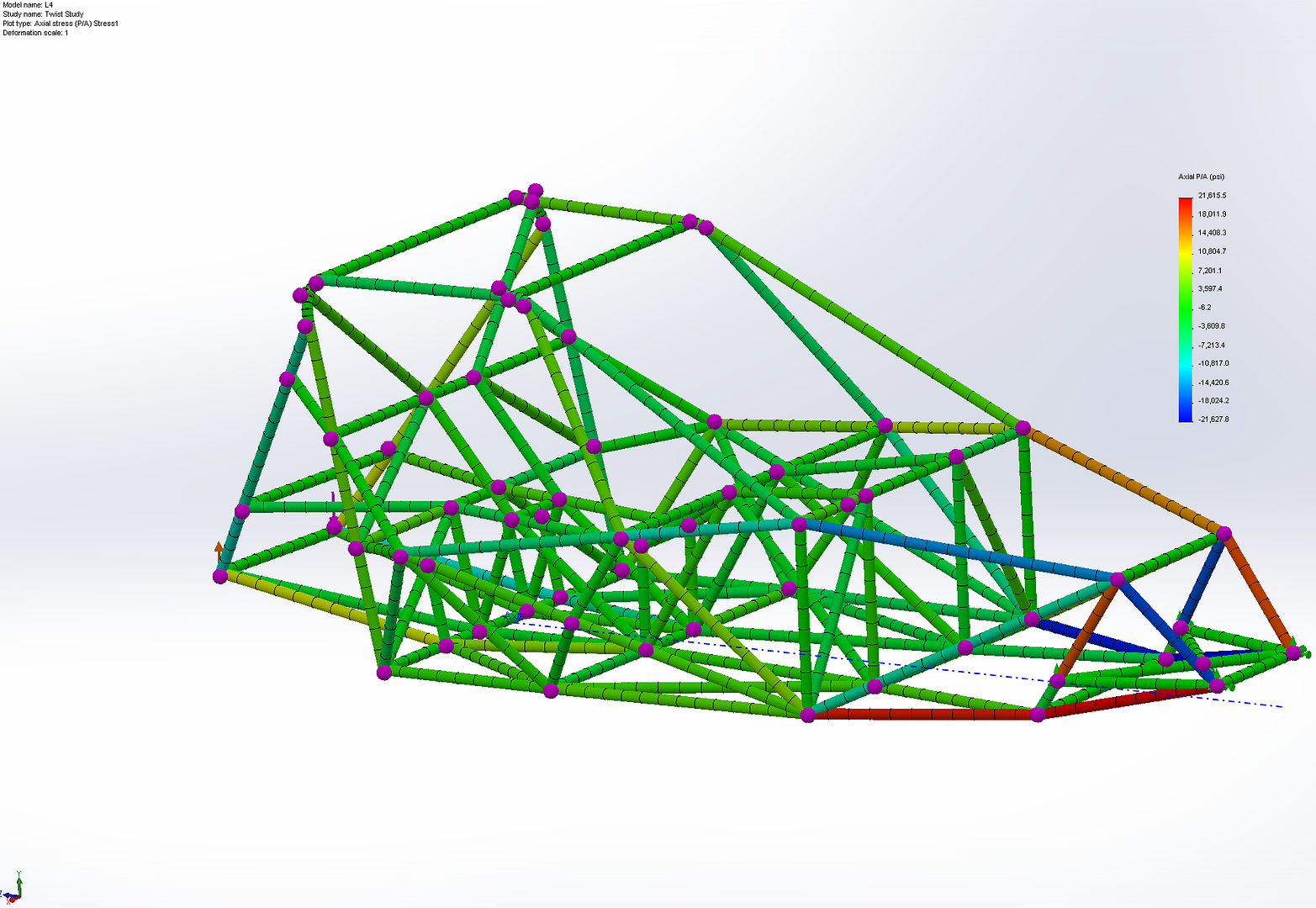
Also, referring to the first picture below of the torsion test I did, load *is* effectively applied to both corners - the reaction force at the jackstand at the front supplies the second one, and will be very similar to an equal and opposite vertical load.
kf2qd wrote:
Ever looked at a railroad car axle? It is not straight. It actually gets smaller in the middle. Years ago I worked for the brother of the guy (Wahl was his last name) who redesigne4d those axles back around WW2. Previously they had been trying to make the axles stronger by making them larger (and stiffer) but they were failing because of the higher loads they were trying to carry. He redesigned the axle with the smaller center so it would have some flex and then axle failures were a thing of the past.
What I am trying to say is this - if you make the frame too stiff then you are transferring all the loads from bumps(impacts) at the tire into a smaller and smaller area of the frame and will probably have to deal with failures at the shock mounts and a-arm mounts. Bumps(impacts) are very short duration, but very high forces. If you stop them over too short a distance then you have to make the frame stronger so that it doesn't fail at the point of impact - the shock mounts and the a-arm connection points. Given - there is some compliance in the shock, but if you have gone to rod ends for your suspension there is very little compliance there. By having some flex in the frame you are reducing the total force that the frame is experiencing. Force = Mass * Acceleration - if you impact the frame with some force (tire in pothole - extreme) and the frame has a minute amount of give (flex) then the total acceleration will be lower so the force the frame has to disipate will be lower. There is some practical limit to what you will be able to gain by stiffeneing the frame, above which you will have to add more weight because the suspension attachment pooints will have to be improved so you won't destroy the frame at those points.
This is true where a more or less fixed deformation (usually bending) is enforced, in which case lower stiffness means lower stress.
But in our case where most of the compliance comes from the suspension and tires, and frame loads are intended to be resolved into tension/compression, more material will mean lower stress in direct proportion.
It may or may not be true (I’d have to analyze it) for lateral loads fed in by the suspension, but it would make more sense to decrease impact loads on the frame by increased bushing compliance than by frame compliance.
a.moore wrote:
Engine bays are such a royal pains in the butt. I may revisit it one of these days - a bolt in brace always seemed appealing. The kicker will be getting the bolted joint stiff enough so the brace is effective and not just ballast.
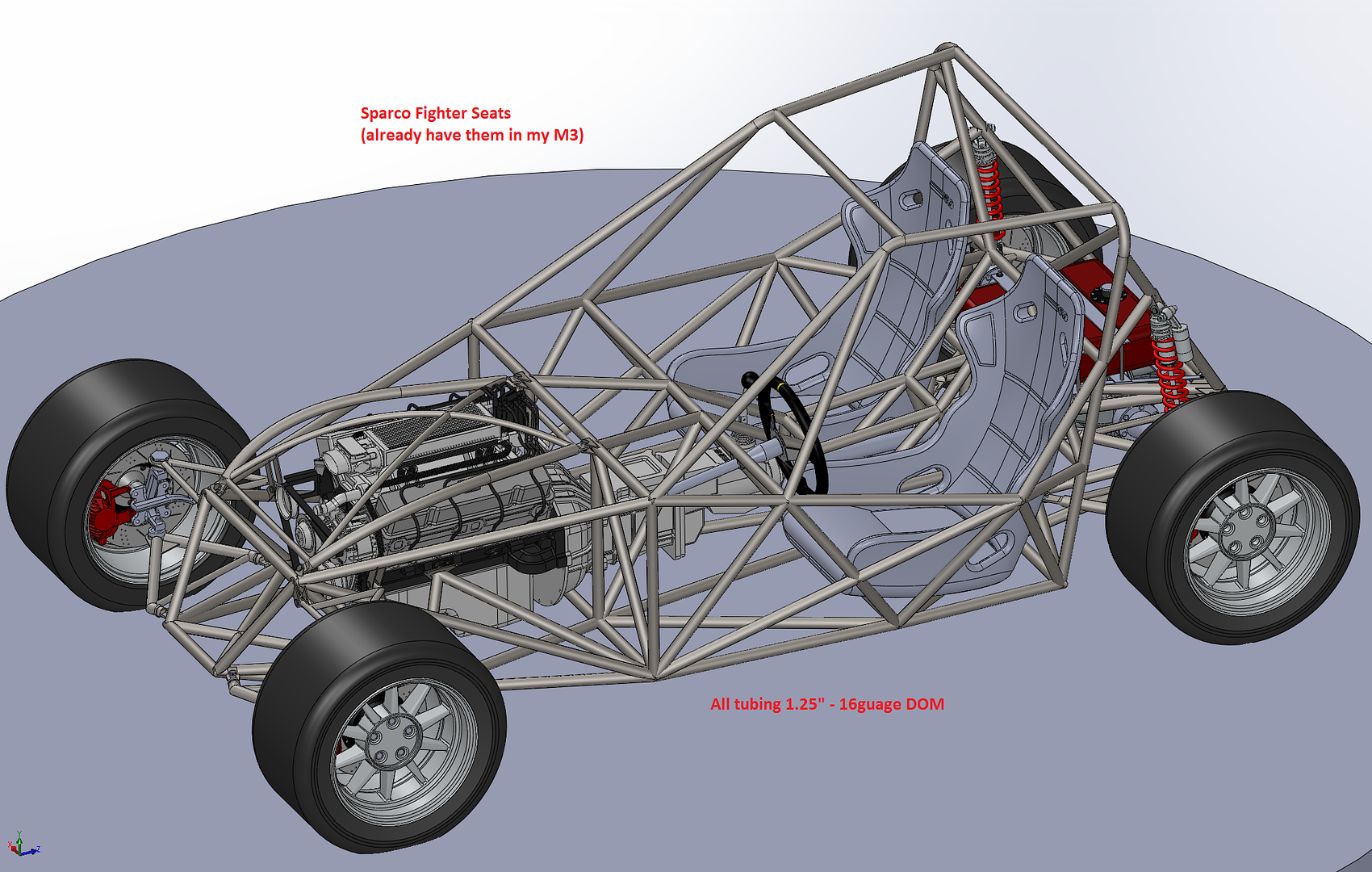
Third pic below shows how I did it on my senior project 3-wheeler frame, which was my first time doing FEA.
The frame weighs 108 lb and stiffness is ~4800 lb-ft/deg.
Lonnie-S wrote:
However, LISA does load and mesh simpler components and does a really cool job of meshing some complex parts. Here is the original Haynes Roadster pedal box meshed by LISA from a STEP file and a separate rendering of it so people can get clear on the geometry, which is hard to see just from the LISA mesh file. This is a 3D, volume mesh.
This part would be much better modeled with 2-D plate/shell elements for both efficiency (run time) and accuracy.
To give reasonable accuracy there should be several layers thick of 3-D elements.
Also they have only 3 DOF per node (the translations) and have no rotational stiffness; every node behaves like a balljoint, which often results in unintended mechanisms in the model.
You can think of 3-D finite elements as “struxels” – structural elements, same as pixels are picture elements; to paint a reasonably accurate picture of the structure, it takes a lot of them.
Whereas the only property assigned to 3-D elements is the material, beam and plate elements are assigned materials and dimensions from which behavior can is calculated using appropriate equations, so you get a whole lot more from each one; it could take hundreds of solid elements to give the same accuracy as one beam element, except at the attach points, where all bets are off..
The key word here is vehicle mass... The lower the vehicle weight, less torsionall stifness is nedeed... so it is a bt pointless (but informative) to compare to a RR...

[/quote]
The proper way to normalize stiffness vs. mass is vibration frequency, as it depends on only those two things.
Decades ago I remember reading in a Road and Track test of a Mercedes that its chassis had achieved 26 Hz.
I presume that the boundary conditions are with the chassis resting on the suspension.
This would be pretty close to what is called free-free, i.e. no restraints, since the suspension is so much more compliant; probably 1 Hz or so, reflecting a relative stiffness of ~1:600.