LocostUSA.com

Learning how to build Lotus Seven replicas...together!
It is currently April 16, 2024, 1:47 am

All times are UTC - 5 hours [ DST ]


Post new topic Reply to topic  [ 9 posts ] 
Author Message
PostPosted: March 14, 2012, 7:12 pm 
Offline
User avatar

Joined: October 23, 2010, 2:40 am
Posts: 1455
I’ve been excited about the Car9 project ever since Horizonjob started his “Messy Shop” thread. So I offered to help Marcus by making Wishbone runs to support his Car9 design effort. For what it is, Wishbone is a great tool at the perfect price ($0). But setting up Wishbone to run requires building a matrix of twenty-four X,Y,Z dimensions which represent the eight suspension pivot points. And these rather esoteric coordinates change with changes in track, wheel offset, tire size, ground clearance and a bunch of other pragmatic, designer-oriented factors. When evolving a new design like Car9 (or when tweaking an older book-derived design) it can become a huge PITA to re-figure the required X,Y,Z’s every time a design change is contemplated and Wishbone is needed to be re-run. I’m sure many of you have experienced this.

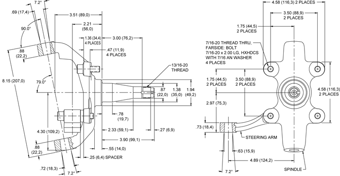
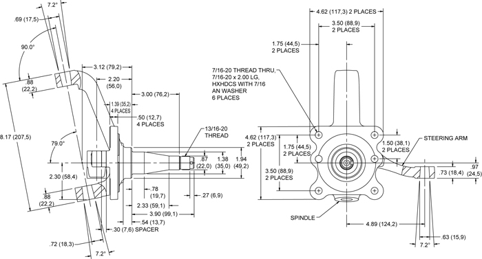
What was missing was a tool to automatically calculate the Wishbone X,Y,Z dimensions directly from the various design parameters. Among the spindle options being considered for Car9 are the Wilwood Mustang II units, which fortuitously have detailed engineering drawings available on the Wilwood website. So, a Wishbone Input Generator was conceived to combine the known Wilwood spindle specs with twenty-two chassis design/set-up parameters and automatically calculate the X,Y,Z’s required. The high school trig books got dusted off :shock: and the Excel spreadsheets included below came to pass.

Here’s how the Wishbone Input Generator is used:

On page 1, the desired design parameters are entered into the Generator: Track width, tire size, wheel offset, ball joint length, rotor hat thickness, etc., etc. Most of the inputs are general design parameters; a few are specific to Wilwood and/or Car9.

On page 2, the twenty-four X,Y,Z dimensions and other items needed to run Wishbone are automatically calculated by Excel. Coordinates for both the standard height and the 2 inch dropped Wilwood spindles are generated.

The coordinate data on page 2 is manually keyed into Wishbone, where one makes multiple roll, bump, steer iterations to analyze a specific geometry in the normal fashion.

In addition to the normal printing, the results of the Wishbone runs can also be recorded (manually again) onto the tables included on pages 3 and 4 of the Generator. As a by-product, swing-arm length is calculated from Wishbone's IC "Z" results and track width. Multiple tables are included so results from different settings of the upper chassis pivot can be more easily compared. These tables are useful in keeping track of (and filing) inputs and results. Otherwise, it’s easy to lose configuration control of what inputs resulted in what outputs. Don’t ask me how I know… :BH:

One could go further and use Excel to plot the various camber curves, etc., but that’s left to the user. And, yes, it would be nice to have the Wishbone input and output automatically transferred to/from the spreadsheet, but that's not implemented.

As mentioned above, the Generator is programmed based on the dimensions and geometry of the Wilwood uprights. The outboard X,Y,Z's are calculated specifically for these units. The inboard X,Y,Z’s are built off these outboard dimensions and are specific to Car9’s chassis and a-arm design. Nevertheless, the concept is valid for other spindles and chassis designs, and the Car9/Wilwood version can be useful in other situations if the differences are taken into consideration. That said, this tool has been a huge help in using Wishbone to analyze multiple Car9 design iterations and suspension configurations in a relatively short period of time.

Two downloadable copies of the Wishbone Input Generator are included in the zip folder below. They are identical, except one has the input parameters and results for a possible Car9 “Track Car” configuration, the other for a possible Car 9 “Street Car”. Both configurations are works-in-process and the design inputs and Wishbone results shown, while getting close, are not final. A Wishbone screen shot for each are also shown below.

Many thanks to Marcus Barrow for his guidance in putting this together, selecting the input data and interpreting the results. And for all his efforts on Car9.

I hope the Generator is useful to other Locosters. Comments and feedback are welcome. There’s always room for improvement.


You do not have the required permissions to view the files attached to this post.

_________________
Cheers, Tom

My Car9 build: viewtopic.php?f=35&t=14613
"It's the construction of the car-the sheer lunacy and joy of making diverse parts come together and work as one-that counts."

Ultima Spyder, Northstar 4.0, Porsche G50/52


Top
 Profile  
Reply with quote  
PostPosted: March 15, 2012, 1:15 am 
Offline
User avatar

Joined: November 7, 2008, 4:48 am
Posts: 1097
Location: snow city - it's wet!
Very nice, lol.

I was actually thinking about different ways to approach this same problem earlier today. I had been considering pulling the data from some type of CAD file as an option. While that makes sense for new designs, it doesn't replace typing the data in by hand for existing cars.

For existing cars, I am considering using string drops, measured lengths, and possibly measured angles to calculate this data. One important goal of my website project is being able to relatively easily reverse engineer these values on existing cars. Some inaccuracy would be inevitable, but this might provide enough accuracy to be able to develop some usable suspension tuning data.

_________________
.. in the world


Last edited by erioshi on March 16, 2012, 11:16 am, edited 1 time in total.

Top
 Profile  
Reply with quote  
PostPosted: March 15, 2012, 12:54 pm 
Offline
User avatar

Joined: December 19, 2006, 11:02 pm
Posts: 81
Location: Willingboro, NJ
Wow! Good stuff, Tom! Thanks for sharing it with us. This is another step forward for locost open source suspension design.

If one were to, oh say for instance, want to apply this to Chevette/Fiero/etc. uprights, what numbers would need to change?

Is there any chance you could hi-light those upright-specific dimensions on your spreadsheet and on a copy of the Wilwood drawing or supply some other graphical reference for the sake of clarity? In other words, something to give people like me, for whom neither the smart-pill nor the placebo seem to be having any discernible effect, a chance to get it. Though I'd be willing to settle for words... :)


-Pete


Top
 Profile  
Reply with quote  
PostPosted: March 15, 2012, 2:40 pm 
Offline
User avatar

Joined: October 23, 2010, 2:40 am
Posts: 1455
erioshi wrote:
Very nice, lol.

I was actually thinking about different ways to approach this same problem earlier today. I had been considering pulling the data from some type of CAD file as an option. While that makes sense for new designs, it doesn't replace typing the data in by hand for existing cars.

For existing cars, I am considering using string drops, measured lengths, and possibly measured angles to calculate this data. One important goal of my website project is being able to relatively easily reverse engineer these values on existing cars. Some inaccuracy would be inevitable, but this might provide enough accuracy to be able to develop some usable suspension tuning data from.
Erioshi, thanks and I agree on the need to get the baseline geometry anyway you can. We were able to create all of it from drawings. Once you have the baseline, its pretty easy to see the effect of changing tire sizes, wheel offsets, ball joint lengths, etc.

Quote:
Wow! Good stuff, Tom! Thanks for sharing it with us. This is another step forward for locost open source suspension design.

If one were to, oh say for instance, want to apply this to Chevette/Fiero/etc. uprights, what numbers would need to change?

Is there any chance you could hi-light those upright-specific dimensions on your spreadsheet and on a copy of the Wilwood drawing or supply some other graphical reference for the sake of clarity? In other words, something to give people like me, for whom neither the smart-pill nor the placebo seem to be having any discernible effect, a chance to get it. Though I'd be willing to settle for words...
Thanks Pete. The Wilwood specific hub length is in spreadsheet row 13 (they offer a variety of hubs to fit these uprights) and the Wilwood upright geometry is imbeded in the formulas within the cells of rows 58-60. The Wilwood drawings are available here http://wilwood.com/Images/Steering/Stee ... dwg-lg.jpg
and here http://wilwood.com/Images/Steering/Stee ... dwg-lg.jpg
If you wanted to apply this approach to Fiero, Miata, etc. uprights you would need to get their geometry/dimensions and update the formulas. Threre is a thread on this forum that has a lot of this info available. I'll leave the math to you (you know what Jimmy Buffet says about math...) :D

BTW, here's a screen shot of some summarized Wishbone results for the Car9 Track Car and Street Car (other suspension settings are in the downloads.) Still a work in progress...


You do not have the required permissions to view the files attached to this post.

_________________
Cheers, Tom

My Car9 build: viewtopic.php?f=35&t=14613
"It's the construction of the car-the sheer lunacy and joy of making diverse parts come together and work as one-that counts."

Ultima Spyder, Northstar 4.0, Porsche G50/52


Top
 Profile  
Reply with quote  
PostPosted: March 15, 2012, 4:26 pm 
Offline
User avatar

Joined: December 19, 2006, 11:02 pm
Posts: 81
Location: Willingboro, NJ
Thanks, Tom. I've got the uprights and ball joints, now I just need to wrestle the dimensions off the peculiar things.


-Pete


Top
 Profile  
Reply with quote  
PostPosted: March 16, 2012, 1:00 pm 
Offline

Joined: June 20, 2010, 6:14 pm
Posts: 94
Location: San Benito TX
Glad to see someone using the Windows version of Wishbone.

I am looking at creating a quick VB program to do the calculations -

Question on your Generator Spreadsheet - Your lower ball joint is lined up with you the lower rearward - can't be changed because of formula. It looks like that is hard coded into your design?


Top
 Profile  
Reply with quote  
PostPosted: March 16, 2012, 4:25 pm 
Offline
User avatar

Joined: October 23, 2010, 2:40 am
Posts: 1455
kf2qd wrote:
Glad to see someone using the Windows version of Wishbone.

I am looking at creating a quick VB program to do the calculations -

Question on your Generator Spreadsheet - Your lower ball joint is lined up with you the lower rearward - can't be changed because of formula. It looks like that is hard coded into your design?
Hi kf2qd, yes, it is imbedded in the spreadsheet cell formulas. All the trig formulas are based on the X = zero line going through the lower balljoints. I originally had X=0 going through the axle line then re-read the original Wishbone documentation which set the LBJ as the zero point and re-did the math to be consistent with the documentation. In the Car9 chassis, the rearward upper/lower a-arm legs are perpendicular to the chassis and the front a-arm legs angle forward. That is why both the lower balljoint and rear lower a-arm pivot both have X=0.

EDIT: The correct placement for X=0 is at the "centre of the wheel" according to McDermott. Version 2.0 of the Generator includes this correction.

If someone wanted to use the Generator for other than Car9's chassis, it would be fairly easy to make a manual adjustment for an angled rear a-arm leg. Any anti-dive numbers would be a little off though.

Edit: Thinking some more about it, it would also be pretty easy to change the spreadsheet to input the +X's and -X's of the four a-arm legs and change a couple of cell formulas. This would make it a more general case. As the spreadsheet exists, rows 25 and 26 already provide for input of the +X's for the forward legs.

Wishbone for Window is working fine. Thanks for doing that!

_________________
Cheers, Tom

My Car9 build: viewtopic.php?f=35&t=14613
"It's the construction of the car-the sheer lunacy and joy of making diverse parts come together and work as one-that counts."

Ultima Spyder, Northstar 4.0, Porsche G50/52


Last edited by seattletom on March 26, 2012, 6:27 pm, edited 1 time in total.

Top
 Profile  
Reply with quote  
PostPosted: March 17, 2012, 5:41 pm 
Offline
User avatar

Joined: October 23, 2010, 2:40 am
Posts: 1455
Below is an updated version of the Wishbone Input Generator. There are two primary changes:

1) The wheel offset calculation has been modified to be consistent with Herb Adams' definition in "Chassis Engineering" which allows for the added width of the wheel rim flanges when measuring wheel backspace. Good catch Horizonjob!

2) The second change allows the user to input the chassis length-wise locations of both the forward and rear pivots of both the upper and lower a-arms. The previous version of the Generator only allowed for locating the forward pivots and assumed the rear a-arm legs were perpendicular to the chassis centerline a'la Car9. This change makes the Generator useful for typical Locost chassis and a-arm designs, as well as for Car9. Thanks for the suggestion kf2qd.

The math in the Generator remains based on the dimensions and geometry of the Wilwood spindles.


You do not have the required permissions to view the files attached to this post.

_________________
Cheers, Tom

My Car9 build: viewtopic.php?f=35&t=14613
"It's the construction of the car-the sheer lunacy and joy of making diverse parts come together and work as one-that counts."

Ultima Spyder, Northstar 4.0, Porsche G50/52


Top
 Profile  
Reply with quote  
PostPosted: March 26, 2012, 6:40 pm 
Offline
User avatar

Joined: October 23, 2010, 2:40 am
Posts: 1455
A downloadable copy of the Wishbone Input Generator V2.0 can be found below. There are two major changes from prior versions.

First, the calculations are now based on X=0 going through the “centre of the wheel” as McDermott puts it. (See Wishbone Definitions post here: viewtopic.php?f=5&t=1438&start=105 ) This is how the math in my draft version had it. But the math in V1.0 and V1.1 (posted previously) was changed to have X=0 go through the lower ball joint. This was based on an early diagram I saw posted in the Wishbone thread and apparently misinterpreted. While this does not seem to affect straight-ahead camber calculations, it would affect steering and CG based calculations. Guess I got wrapped around the proverbial axle and got off on a tangent. :BH: Anyway, the math in V2.0 has X=0 back where it belongs at the “centre of the wheel.”

The second change in Wishbone Input Generator V2.0 is in how the a-arm parameters are input. This change simplifies describing different a-arm designs and should also simplify making anti-dive/squat adjustments.

One caveat when adjusting anti-dive/squat: The Z dimension (width) of an inboard a-arm pivot is calculated based on the height of the pivot and the vertical angle (flair) of the bulkhead to which the pivot is attached. In adjusting anti-dive/squat, one may set different heights for the inboard fore and aft pivots of an a-arm. This could result in different Z values for that a-arm’s inner pivots, causing a pigeon-toed or splayed effect. This in turn could cause undesirable suspension geometry. In this case, it may be necessary to manually adjust these Z values before entering them into Wishbone to set the inboard a-arm pivots parallel to the chassis centerline. In this situation, the Z value for the inboard tie-rod end (Toe Control Arm) may also need adjustment to minimize bump steer. If fore/aft pivot heights are the same, then the Z values are good as calculated. Caveat emptor.

Wishbone Input Generator V2.0’s geometry calculations are based on the Wilwood Mustang II front uprights. The chassis-side calculations and a-arm shapes are not specific to particular chassis or a-arm designs.

Hope this is useful to other locosters.


You do not have the required permissions to view the files attached to this post.

_________________
Cheers, Tom

My Car9 build: viewtopic.php?f=35&t=14613
"It's the construction of the car-the sheer lunacy and joy of making diverse parts come together and work as one-that counts."

Ultima Spyder, Northstar 4.0, Porsche G50/52


Top
 Profile  
Reply with quote  
Display posts from previous:  Sort by  
Post new topic Reply to topic  [ 9 posts ] 

All times are UTC - 5 hours [ DST ]


Who is online

Users browsing this forum: No registered users and 2 guests


You cannot post new topics in this forum
You cannot reply to topics in this forum
You cannot edit your posts in this forum
You cannot delete your posts in this forum
You cannot post attachments in this forum

Jump to:  
POWERED_BY