LocostUSA.com

Learning how to build Lotus Seven replicas...together!
It is currently April 18, 2024, 11:28 am

All times are UTC - 5 hours [ DST ]


Post new topic Reply to topic  [ 373 posts ]  Go to page Previous  1, 2, 3, 4, 5, 6, 7 ... 25  Next
Author Message
PostPosted: September 17, 2014, 6:51 am 
Offline
The voice of reason
User avatar

Joined: January 10, 2008, 4:47 pm
Posts: 7652
Location: Massachusetts
The toe control link will need to be a compromise of length and angle between the upper and lower link to prevent bump steer, parallel to the lower arm would be close but not right.

Maybe you can ditch some of that subframe and run the trailing part of the lower arm to the roll bar. Then build a stronger trailing arm and mount the shock directly to that? Anyway maybe there would be a way to get rid of that spacer at the bottom of the shock.

_________________
Marcus Barrow - Car9 an open design community supported sports car for home builders!
SketchUp collection for LocostUSA: "Dream it, Build it, Drive it!"
Car9 Roadster information - models, drawings, resources etc.


Top
 Profile  
Reply with quote  
PostPosted: September 17, 2014, 8:00 am 
Offline
User avatar

Joined: August 18, 2014, 11:20 pm
Posts: 185
Location: San Antonio, Texas
With regards to the inboard toe link pickup point, could you further explain?

I agree I can make a new LCA and more easily place the bottom of the damper between the splay. I'm already thinking about ditching the use of the subframes, as I can get 2"x2" square tube 4130 at a reasonable price.

I would essentially jig the engine/trans/axles with mounts between the rear uprights and main roll hoop and begin to connect the dots. My fabrication skills certainly aren't as good as my techs at work, but I can get help with fab work if need be.

A few things have come up with regards to engine placement. What is the minimum distance between the engine and firewall such that I don't BBQ my back from heat radiating from the headers? I've got about 3.75" at the moment, which will be filled with double aluminum sheet and insulating material, and a header heat shield. A 30 minute session at MSR Houston would likely get the engine bay nice and toasty.

Ride height. Other engineers at my office are concerned cars on the road won't be able to see me, as the car has a 3" ride height and is barely 40" tall. But I explained this car will be about as tall as a lowered Miata with its top down.

_________________
There is no such thing as mechanical failure, only a lack of attention to detail.


Top
 Profile  
Reply with quote  
PostPosted: September 17, 2014, 12:46 pm 
Offline
User avatar

Joined: October 23, 2010, 2:40 am
Posts: 1455
LateralScience wrote:

The governing expressions are on the right, and the input and output values are on the left. The upper triangle is at rest, and the bottom triangle is under bump displacement d. Let me know if someone is interested in verifying my math, as there may be something that I'm missing.

Front:
Attachment:
Front IR.jpg


LateralS, Would you mind posting or PM'ing me the spreadsheet? While I'm more interested in using it than checking it :oops: I could also take a look at the math. You would need to package it as a zip file either way. Thanks.

_________________
Cheers, Tom

My Car9 build: viewtopic.php?f=35&t=14613
"It's the construction of the car-the sheer lunacy and joy of making diverse parts come together and work as one-that counts."

Ultima Spyder, Northstar 4.0, Porsche G50/52


Top
 Profile  
Reply with quote  
PostPosted: September 17, 2014, 6:10 pm 
Offline
Automotive Encyclopedia
User avatar

Joined: December 22, 2006, 2:05 pm
Posts: 8042
LateralScience wrote:
The options here I see are:
-clock the engine 90 degrees forward to raise the inboard axle pickup point (necessitating a dry sump)
-design around 13" wheels with a 10.2" wheel hub centerline
-run the CV joint horizontal to outboard chains/gears to allow for engine lowering. (Not likely to happen).

So the trade off here is high CG with a better CV axle angle, or a low CG with a bad CV angle. Any thoughts?


Run smaller od tires, limit compression of the suspension and raise the drive line if necessary. A loss of some efficiency in the transfer for such an overpowered machine is more for the cart than horse.

On the bump steer, the lca has an arc of travel. Only if the uca were parallel and equal length to the lca would the toe link boss on the upright travel in a parallel arc to the lca. I suggest you build the toe link and inner mount after mock up and checking of the finished and aligned (with mocked up toe link and camber) rear suspension.

_________________
Miata UBJ: ES-2074R('70s maz pickup)
Ford IFS viewtopic.php?f=5&t=13225&p=134742
Simple Spring select viewtopic.php?f=5&t=11815
LxWxHt
360LA 442E: 134.5x46x15
Lotus7:115x39x7.25
Tiger Avon:114x40x13.3-12.6
Champion/Book:114x42x11
Gibbs/Haynes:122x42x14
VoDou:113x44x14
McSorley 442:122x46x14
Collins 241:127x46x12


Top
 Profile  
Reply with quote  
PostPosted: September 17, 2014, 7:47 pm 
Offline
User avatar

Joined: August 18, 2014, 11:20 pm
Posts: 185
Location: San Antonio, Texas
I appreciate the explanation. I believe we used Optimum K in FSAE and iterated on inboard toe link points until we arrived at nearly zero toe change in bump and droop, without deriving the equations of motions ourselves--not good engineering practice.

As per CV angle, I think you're correct as I could probably stand to lose a few horses. While out to lunch today I had the chance to drive my colleagues 997 Carrera S--which was plenty fast for me at 8.8 lbs per hp. (355hp, 3131 lbs). With "Buford" at 4.9 lbs/hp I should be satisfied.

I'm adding an UCA and upright to my excel calculator to look at negative camber as a function of UCA angle and pickup location. (Damn it, I was afraid this would happen...doing trig calcs instead of cutting metal.)

_________________
There is no such thing as mechanical failure, only a lack of attention to detail.


Top
 Profile  
Reply with quote  
PostPosted: September 17, 2014, 7:53 pm 
Offline
User avatar

Joined: August 18, 2014, 11:20 pm
Posts: 185
Location: San Antonio, Texas
Also, I'm planning on going with a Bassett 13x9 wheel, and use a 10" wheel centerline height. There are just too many advantages going with a smaller wheel: lower CG, better CV angle, reduced rotating inertia, reduced unsprung mass, shorter overall gear ratios (more force applied at contact patch), availability of cheap sticky 9.5" used Hoosier rubber.

Plus toyo offers the R888 in a 225/45r13 for street use.

_________________
There is no such thing as mechanical failure, only a lack of attention to detail.


Top
 Profile  
Reply with quote  
PostPosted: September 18, 2014, 12:08 am 
Offline
User avatar

Joined: August 18, 2014, 11:20 pm
Posts: 185
Location: San Antonio, Texas
Gents,

I started mocking up a bare block and trans. The engine oil pan and transmission is placed to have 4" of ground clearance. I started playing with the idea of lowering the engine even further, however the thought of a sharp bump in the concrete ripping a hole in the oil pan would be horrible.

I'll most certainly need to buy more wood and strenghten the table as well as build appropriate stand-offs to locate and support vital components.

I took apart the uprights, and pounded out the lower ball joint. Considering how much load goes to the ball joint support on the upright, (essentially accelerating, braking and cornering a 2600 lb car) it really is amazing how little material there enclosing it. About a 0.25"x0.5" cross section of cast iron. I guessing Honda must have had some form of FEA back in the late 1980's.

I took a few measurements of the CV angle using a 13" wheel vs. a 16" wheel, and the differences were astounding. With a transmission output shaft centerline at 9" above the ground, the CV angle for a 13" wheel was 4 degrees:
Attachment:
CV angle with 13 inch wheel.jpg


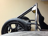
With the 16" wheel, the CV angle is 15 degrees:
Attachment:
CV angle with 16 inch wheel.jpg


I'm fairly sure there are a few ASME or SAE articles characterizing spin loss and efficiency of Rzeppa CV axles as a function of angle, speed, and torque. Needless to say, 13" wheels it is. Does anyone know if NB miata spindles can accept 4 piston wilwood dynalite calipers under 13" wheels? I tried to search for a willwood bracket which allows for the stock miata rotor to be used with wilwood calipers and have found nothing.


You do not have the required permissions to view the files attached to this post.

_________________
There is no such thing as mechanical failure, only a lack of attention to detail.


Top
 Profile  
Reply with quote  
PostPosted: September 18, 2014, 10:14 am 
Offline
Automotive Encyclopedia
User avatar

Joined: December 22, 2006, 2:05 pm
Posts: 8042
I think you can only use 90-93 rotors with 13" rims, with little to no gain in clearance by adapting wilwood calipers (though I understand the other reasons for converting to Wilwoods). Not sure though.

Wilwood has charts of the caliper outside corner distance to the axle centerline, based on rotor ods.

Might try miata.net classifieds for a second hand 90-93 wilwood kit and spindles, no doubt sitting on a shelf.

_________________
Miata UBJ: ES-2074R('70s maz pickup)
Ford IFS viewtopic.php?f=5&t=13225&p=134742
Simple Spring select viewtopic.php?f=5&t=11815
LxWxHt
360LA 442E: 134.5x46x15
Lotus7:115x39x7.25
Tiger Avon:114x40x13.3-12.6
Champion/Book:114x42x11
Gibbs/Haynes:122x42x14
VoDou:113x44x14
McSorley 442:122x46x14
Collins 241:127x46x12


Top
 Profile  
Reply with quote  
PostPosted: September 18, 2014, 11:15 am 
Offline
Toyotaphobe
User avatar

Joined: April 5, 2008, 2:25 am
Posts: 4829
Location: Fort Worth, Texas
The thing to do is not try to get the same ground clearance with the 16" tire, but to use the 16" on the road and the 13" on the track that way you keep the same geometry but gain the ground clearance for the road

_________________
mobilito ergo sum
I drive therefore I am

I can explain it to you,
but I can't understand it for you.


Top
 Profile  
Reply with quote  
PostPosted: September 18, 2014, 1:54 pm 
Offline
User avatar

Joined: August 18, 2014, 11:20 pm
Posts: 185
Location: San Antonio, Texas
Agreed. I will design with a 13" wheel in mind, and change over to 16" wheels when on the street, which will give me a 5" ground clearance. I showed the 15 degree CV angle to one of our Drivetrain engineers at my work in passing, and he was adamant the CV joint will not only lose efficiency, but generate tremendous heat as well and more quickly breakdown the grease and wear out the joint prematurely.

_________________
There is no such thing as mechanical failure, only a lack of attention to detail.


Top
 Profile  
Reply with quote  
PostPosted: September 18, 2014, 2:45 pm 
Offline

Joined: August 19, 2014, 5:17 pm
Posts: 685
Location: England
LateralScience wrote:
Agreed. I will design with a 13" wheel in mind, and change over to 16" wheels when on the street, which will give me a 5" ground clearance. I showed the 15 degree CV angle to one of our Drivetrain engineers at my work in passing, and he was adamant the CV joint will not only lose efficiency, but generate tremendous heat as well and more quickly breakdown the grease and wear out the joint prematurely.


Would it not pay to lean the engine forward as far as possible which would in turn lift the driveshaft centerline and maybe strike a happy medium between the two wheel sizes. Maybe just alter the sump and pickup to accommodate, this would also lower the cg even further. Alternatively fit an adaptor plate between the engine and box and rotate the box in relationship to the engine.
Just thoughts .

bob

_________________
Build Log viewtopic.php?f=35&t=16640&p=187700#p187700

Mancave http://s1116.photobucket.com/user/mypic ... ow/mancave


Top
 Profile  
Reply with quote  
PostPosted: September 18, 2014, 3:47 pm 
Offline
The voice of reason
User avatar

Joined: January 10, 2008, 4:47 pm
Posts: 7652
Location: Massachusetts
Quote:
lose efficiency, but generate tremendous heat as well and more quickly breakdown the grease and wear out the joint prematurely.


Yes and these are the same thing! One horsepower is about 750 Watts. Watts is the metric unit for horsepower. When people say you are losing %10 of your power in the drivetrain, imagine 10 Hp as 7500 watts - that's about 5 household space heaters.

Is the picture of the upright for 16" wheels only raised 1.5"? It looks more but maybe not.

_________________
Marcus Barrow - Car9 an open design community supported sports car for home builders!
SketchUp collection for LocostUSA: "Dream it, Build it, Drive it!"
Car9 Roadster information - models, drawings, resources etc.


Top
 Profile  
Reply with quote  
PostPosted: September 18, 2014, 4:33 pm 
Offline
User avatar

Joined: August 18, 2014, 11:20 pm
Posts: 185
Location: San Antonio, Texas
Erm...Power is simply work over time. Efficiency is a unitless ratio of power out over power in.

_________________
There is no such thing as mechanical failure, only a lack of attention to detail.


Top
 Profile  
Reply with quote  
PostPosted: September 18, 2014, 5:17 pm 
Offline
The voice of reason
User avatar

Joined: January 10, 2008, 4:47 pm
Posts: 7652
Location: Massachusetts
It's inefficient because it's consuming some power. If you estimate how much power is lost, any significant amount of horsepower is a lot of watts going into something like a CV joint. I'm sorry if it seemed I was belaboring a point or being obvious....

_________________
Marcus Barrow - Car9 an open design community supported sports car for home builders!
SketchUp collection for LocostUSA: "Dream it, Build it, Drive it!"
Car9 Roadster information - models, drawings, resources etc.


Top
 Profile  
Reply with quote  
PostPosted: September 18, 2014, 8:26 pm 
Offline
User avatar

Joined: August 18, 2014, 11:20 pm
Posts: 185
Location: San Antonio, Texas
seattletom,

PM has been sent with the excel spreadsheet. I added descriptions in the headers explaining the variable.

(DISCLAIMER: Note that I make no claims of accuracy of the calculations. Therefore, I do not hold myself responsible for the usage of the calculations if in the event vehicular damage (or any damage) or bodily harm occurs from inaccuracies in the calculations.)

Enjoy!

_________________
There is no such thing as mechanical failure, only a lack of attention to detail.


Top
 Profile  
Reply with quote  
Display posts from previous:  Sort by  
Post new topic Reply to topic  [ 373 posts ]  Go to page Previous  1, 2, 3, 4, 5, 6, 7 ... 25  Next

All times are UTC - 5 hours [ DST ]


Who is online

Users browsing this forum: No registered users and 23 guests


You cannot post new topics in this forum
You cannot reply to topics in this forum
You cannot edit your posts in this forum
You cannot delete your posts in this forum
You cannot post attachments in this forum

Jump to:  
POWERED_BY