LocostUSA.com

Learning how to build Lotus Seven replicas...together!
It is currently April 18, 2024, 5:57 am

All times are UTC - 5 hours [ DST ]


Post new topic Reply to topic  [ 373 posts ]  Go to page Previous  1, 2, 3, 4, 5, 6, 7, 8 ... 25  Next
Author Message
PostPosted: September 18, 2014, 8:53 pm 
Offline
User avatar

Joined: August 18, 2014, 11:20 pm
Posts: 185
Location: San Antonio, Texas
This evening I machined 1/2" holes in the uprights for the UCA pickup outboard points.

As expected, this took longer than anticipated, and indicated the hub centerline perpendicular to the hole. Also, the placement of the centerline of the hole MUST have the same distance between the UCA pickup point and axle centerline. Checking and rechecking the cut of the 2nd upright hole to be identical with the first was a bit tedious.

Nevertheless, I'm satisfied with the results:
Attachment:
UCA outboard pickup points drilled into upright.jpg

I'm fairly confident the placement of the hole in both the horizontal and vertical planes are +/- 0.007".

Verifying horizontal placement of the cut with respect to the outboard LCA pickup point and axle centerline (using toe link for parallelism):
Attachment:
Checking for horizontal axis of drilling relative to axle centerline.jpg


I am planning on pressing out the hub bearings and replacing them with Timken units, but the hydraulic press was unable to fully press them out. I'm not quite sure why the bearing is being hung up, but perhaps I just need to try a stronger press. There are no snap rings or retaining clips to remove. Anyone here have any experience pressing out wheel bearings on a 1990 Acura Integra?


You do not have the required permissions to view the files attached to this post.

_________________
There is no such thing as mechanical failure, only a lack of attention to detail.


Top
 Profile  
Reply with quote  
PostPosted: September 18, 2014, 10:26 pm 
Offline
User avatar

Joined: August 18, 2014, 11:20 pm
Posts: 185
Location: San Antonio, Texas
While on the subject of uprights, the front miata uprights came in the mail today. Dealing with dimensions of class 8 trucks all day, kinda made me giggle when I saw how small these parts are:
Attachment:
miata front upright.jpg


Compared with a glass of moscato:
Attachment:
miata upright size comparison.jpg


Rod ends will be 5/8-18 heim, with a 1/2" dia grade 8 bolt, using 1" OD 0.095" wall AFCO swaged tubes. Factor of safety against yield of 14 for the 1/2" bolt in double shear, with a 2000 lbf load per tube. WAY overbuilt for this application. I could save some weight by going with 3/8-24 heims, but I havn't found any swaged tubes in 3/8-24 as cheap as AFCO threaded tubes, thus tube-end weld in bungs would be needed, as would 3/4" 0.065" 4130 tubing, which drives up the overall cost.

So 5/8-18 heims it is, despite the slight increase in unsprung weight. But the excessive FoS would give me piece of mind if I ever hit a terrible section of asphalt.


You do not have the required permissions to view the files attached to this post.

_________________
There is no such thing as mechanical failure, only a lack of attention to detail.


Top
 Profile  
Reply with quote  
PostPosted: September 19, 2014, 7:00 am 
Offline
Automotive Encyclopedia
User avatar

Joined: December 22, 2006, 2:05 pm
Posts: 8042
Erm, press the center hub from the bearing to expose the snap ring before you break something.

Sorry, couldn't resist! Of course, nobody here has ever made a mistake... :roll:

_________________
Miata UBJ: ES-2074R('70s maz pickup)
Ford IFS viewtopic.php?f=5&t=13225&p=134742
Simple Spring select viewtopic.php?f=5&t=11815
LxWxHt
360LA 442E: 134.5x46x15
Lotus7:115x39x7.25
Tiger Avon:114x40x13.3-12.6
Champion/Book:114x42x11
Gibbs/Haynes:122x42x14
VoDou:113x44x14
McSorley 442:122x46x14
Collins 241:127x46x12


Top
 Profile  
Reply with quote  
PostPosted: September 19, 2014, 7:51 am 
Offline
User avatar

Joined: August 18, 2014, 11:20 pm
Posts: 185
Location: San Antonio, Texas
It wouldn't be the first time I broke something--and not likely to be the last. :oops:

I'll see if I have deformed the groove retaining the C clip. I'm impressed the upright didn't fracture, and was able to stop the press.

_________________
There is no such thing as mechanical failure, only a lack of attention to detail.


Top
 Profile  
Reply with quote  
PostPosted: September 19, 2014, 11:43 pm 
Offline
User avatar

Joined: August 18, 2014, 11:20 pm
Posts: 185
Location: San Antonio, Texas
Not too much progress today. But I did get the bearings out of the integra uprights:
Attachment:
bearings out.jpg


Miatav8,MstrASE,A&P,F, You were correct. As suspected, I nicked the snap ring groove inside the upright.
Attachment:
nicked snap ring land.jpg

I think it will be okay though. Most of the load applied to the bearing will be inboard of the snap ring.

I placed an order for 16 right hand 5/8-16 heims, and 16 left hand 5/8-16 heims. These are WAY over built for a 1200~1300 lb car, but I'd much rather be on the safe side. I would also like the ability to adjust damn near everything such that I can continually tune the suspension.

I plan on using a 5/8-16 rod ends everywhere:
Front and Rear UCA inboard and outboard points
Front and Rear LCA inboard and outboard points
Front Tie rod links
Rear Toe links

I'm still on the fence if I'm going direct actuation or bell crank pull/pushrod. It would be great to be able to change ride height WITHOUT loss of spring/damper travel via pushrod length.

The pushrod suspension below doesn't see too difficult to fabricate. It looks like AFCO swaged steel tubes as pushrods, and an IR of 2? (Correct me if i am wrong.)
Attachment:
pushrod example.jpg

Also, it looks like the pushrod is 90 degrees to the bellcrank, and the damper is 90 degrees to the bellcrank. (90 degrees is ALOT easier to manufacture/fabricate to than odd angles without a frame of reference to judge by. This configuration would seemingly provide supple and neutral handling I would assume.


You do not have the required permissions to view the files attached to this post.

_________________
There is no such thing as mechanical failure, only a lack of attention to detail.


Top
 Profile  
Reply with quote  
PostPosted: September 20, 2014, 11:55 pm 
Offline
User avatar

Joined: July 4, 2006, 5:40 pm
Posts: 1994
Location: Novato, CA
I'm curious if anyone who built a Locost with inboard suspension would do it again. I suppose they might if they thought they could get it right the second time. To me it always seemed like a lot of work just to block your airflow through the radiator.


Top
 Profile  
Reply with quote  
PostPosted: September 21, 2014, 1:17 am 
Offline
User avatar

Joined: August 18, 2014, 11:20 pm
Posts: 185
Location: San Antonio, Texas
I believe the car above was a BEC designed as a purpose built racecar with an R1 engine. The radiator is placed flat behind the springs/dampers, and draws air from underneath the car.

It's possible to place the radiator outside the front end assembly tubes, and duct the airflow out of the radiator upwards away from the springs/dampers through cut louvers in the hood.

The big upsides I see with inboard suspension is the ability to change ride height without reducing damper/spring travel, as well as reduced unsprung weight, and reduced polar moment of intertia in roll (and possibly yaw), as well as being able to change wheel rate simply by swapping out to a different bell crank with a different motion ratio. (A reduction in frontal area occurs as well, but a Lotus7 is essentially as aero as a brick anyway.)

The added monkey motion is a pain to package, and does add to the overall weight of the car.

----------------

As per progress today, I began fully welding the front and mid portions of the chassis, as well as mated the main roll hoop to the standard book chassis frame.

Round tube notching is most certainly an art form which I am not very good at:
Attachment:
drivers side main roll hoop to book chassis notch.jpg


I ended up removing redundant members B1, K3, K4, O3, and O. Also member M1 and M2 of the book chassis now triangulate with the main roll hoop.

Outboard of node joining main roll hoop base to B1, A2, and M2:
Attachment:
Passenger side outboard node of mainroll hoop to B1, A2 and M2 members.jpg


After a bit of practice, I nervously jumped in and started fully welding the chassis nodes:
Attachment:
Fully welding the chassis begins....jpg

I'm not very pleased with the results in some areas, as the bead is relatively high, with prominent splatter as you can see. I'm most certainly open to ideas of improving if folks have any pointers for me. When I pull the gun out upon ending a weld, I get a tiny little pinhole. My settings on my machine are as follows:

Lincoln SP135T MIG welder
Heat: D
Wire Feed: 4.5
Sheilding gas flow rate (Argon/CO2 mix): 20 CFPH
0.025" MIG wire
~0.25" stick out
Gas nozzle set to flush with tip

--------

After running out of sheilding gas I put the chassis at ride height and threw the seat in it, and placed the wheels and tires around it.
Attachment:
This is madness...no this is Locost7.jpg

With a 3" ride height, this thing is about waist tall. This really is a toy car. One day I'll grow up. Until then, I'm going to make engine noises whilst sitting in the Momo.


You do not have the required permissions to view the files attached to this post.

_________________
There is no such thing as mechanical failure, only a lack of attention to detail.


Top
 Profile  
Reply with quote  
PostPosted: September 21, 2014, 1:46 am 
Offline
User avatar

Joined: April 19, 2012, 9:43 pm
Posts: 419
Location: Colorado
Some potential help on the welding:

1. Don't stop in a corner, work it so you start and stop on the face.

2. You may be pulling the torch out before letting off the trigger. This creates a more pronounced crater. Make sure you hold the torch in place when you let off the trigger. If you aren't pulling out then you may need some countermeasures like a small forward back forward motion or a start stop pulse to fill in.

3. I think you may be working with a little too much wire out. Try moving in a bit closer (maybe half the distance as a guesstimate).

It's certainly not a worrisome weld and I may be totally off base on how to make it better. I'm not a weld inspector or someone who really knows the ins and outs of this so grain of salt and use a test piece to verify sortah situation.


Top
 Profile  
Reply with quote  
PostPosted: September 21, 2014, 10:03 am 
Offline
The voice of reason
User avatar

Joined: January 10, 2008, 4:47 pm
Posts: 7652
Location: Massachusetts
I try to end on a tack weld to cut down on cratering at the end of a run. It's a good idea to tack all four corners before you weld.

Practice on some round tube before you weld the round tube in your chassis. I did a lot of practice on square tube and then noticed my welds tend to be straight even when welding round tube. It's a different motion obviously... :rofl:

_________________
Marcus Barrow - Car9 an open design community supported sports car for home builders!
SketchUp collection for LocostUSA: "Dream it, Build it, Drive it!"
Car9 Roadster information - models, drawings, resources etc.


Top
 Profile  
Reply with quote  
PostPosted: September 21, 2014, 10:36 am 
Offline
User avatar

Joined: April 19, 2012, 9:43 pm
Posts: 419
Location: Colorado
That is a great tip. Ending the bead on your tacks is the easiest way to prevent most cratering.


Top
 Profile  
Reply with quote  
PostPosted: September 21, 2014, 11:44 pm 
Offline
User avatar

Joined: August 18, 2014, 11:20 pm
Posts: 185
Location: San Antonio, Texas
Gents,

I appreciate the welding suggestions. I'll give that I try after I obtain more shielding gas tomorrow. These small 20 cubic ft bottles are handy to store, but are really only good for 15~20 minutes of welding. I could drop my flowrate down a little, however I would run the risk of contaminating the weld. A new big bottle simply isn't in the budget, but I'm in the market for a used big one.

With regards to progress today, the chassis table was extended 2ft, and widened about 14" at each corner to support the wheels/tires. Not the most beauteous woodworking, but hey, it's sturdy enough to support the front corners:
Attachment:
additions to the table.jpg


Luckily I was able to source Aerospace grade wood certified to ISO9001 specifications, as indicated by the appropriate markings (I'm kidding):
Attachment:
Aerospace Grade ISO9001 wood.jpg


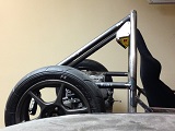
I did get a chance to raise the engine to 8.75" axle centerline above the table, with the chassis flat on the table. This would give me a horizontal axle with a 3" chassis clearance. I did think about clocking the engine 45 degrees towards the front, remake a new oil pickup tube, and make a custom oil pan to drop the sump down and forward to ensure the crank is not submerged in oil. However, a bell crank shifter linkage would need to be fabricated in a such an orientation, and the Acura Integra shifter linkages could not be then be utilized.
Attachment:
Axle centerline at 8.75 inches with normal engine placement, with chassis FLAT on table.jpg


In terms of members rearward of the main roll hoop to support the engine, and rear control arms, I am going with an engine installation and extraction from the bottom. It is alot easier to install the chassis over the engine than vice-versa, as the engine is ALOT heavier than the chassis. Also, an engine hoist would not be required, and packaging seems easier.

With regards to the placement of the tubes, there will be left and right primary "booms" placed horizontally which will tie into the main roll hoop at the top of the triangulation members. The left side boom will intercept the LUCA inboard points, and engine mount (crank pulley side) point.
Attachment:
left side boom intercepting pickup points LUCA and engine mount crank pulley side.jpg


The right side "boom" will intercept the RUCA and transmission mount points.
Attachment:
Right chassis member boom intercepting pickup points RUCA and Trans mount.jpg


Since the "booms" will be cantilevered members placed in compression along its axial direction, three other tubes will tie into the Upper Rear control arm members:
1) Longitudinal member starting from first bend in the main roll hoop
2) Diagonal X-brace member which ties in from opposite side of the main roll hoop at 2nd bend
3) Rear Lateral Member supporting both the rear engine mount

Looking at the chassis from the rear, this would essentially look like a square with an X within it. Similar to what the Kimini looked like:
Attachment:
Kimini.JPG


I believe this configuration works well as the members supporting the booms will be in tension with the exception of the rear lateral member. The rear member must be relatively stiff in compression to resist buckling. Furthermore, from what I recall of the Dugoff tire model in school, the resultant tire force vector acting on the tire contact patch area is behind the area centroid of the tire footprint.

Also, it appears my Locost7 comes with heated seats as a standard option:
Attachment:
Heated seats as standard.jpg


I may need to move the seat forward, and increase the distance between the header and main roll hoop. Even with aluminum sheets and insulating material, this will get mighty toasty.


You do not have the required permissions to view the files attached to this post.

_________________
There is no such thing as mechanical failure, only a lack of attention to detail.


Top
 Profile  
Reply with quote  
PostPosted: September 23, 2014, 12:13 am 
Offline
User avatar

Joined: August 18, 2014, 11:20 pm
Posts: 185
Location: San Antonio, Texas
In planning the rear chassis member tubing, I bit the bullet and ordered 24 ft of 4130 in 1.75" OD and 0.095". I was initially going with the plan of not using 4130, but considering the large loads placed on the rear chassis members, I had better make sure the structure is strong.

While waiting on build materials for the rear, I've begun to think about the front suspension.

I am trying to ensure redundant tubes are not added to the chassis without some thought as to the manner in which that member is loaded. In essence, each tube should be loaded in either tension or compression and almost NEVER in bending. From what I recall in FSAE design reviews, if ALL of the chassis tubes were made of string, you should be able to "lift" the car up by the wheels, and the chassis string members should all be taught and in tension, without any sagging strings, or strings in compression. Furthermore, there should be no two identical tubes along the longitudinal direction of the chassis as the stresses throughout the chassis are not uniform, therefore the chassis tubes should not be uniform. Obviously this is more of a design for stiffness and weight optimization where ANSYS or NASTRAN would be best applied.

One area where I commonly see tubes placed in bending on the Locost7 chassis are at the front inboard lower control arm points:
Attachment:
UCA inboard point not supported.jpg


Another thing that I am seeing is placing the threaded shank of the rod end in bending, as well as placing tubes in bending:
Attachment:
tube in bending and rod end shank in bending.jpg


Considering the root of the threaded bolt is essentially a crack from which to propagate, when subjected to bending loads, it is more likely to fail. It is possible to split the difference, and subject the leading and trailing pickup points to distribute the bending load more evenly.
Attachment:
AlMurray-Brabham-BT21-CG.jpg


My thoughts are to load the arms only in tension and compression, and load the large 1/2" grade 8 bolt at the upright in single shear. (Which still gives a Factor of Safety against yield of 16.6 with a 2000lbf load.)
Attachment:
miata_front_spindle drawn.jpg

This would allow for easy caster and camber adjustment, without loading members in bending, and without the need to weld upper control arms. Note that this would effectively increase the height of the upright, as the pivot point of the upright would be between the spherical bearings. Granted this would add 1 extra heim joint per corner. Also I'm thinking about going with AFCO 36216 Swedged Aluminum Tube, 1 Inch O.D.(5/8) Inch to save weight. Plus the aluminum tube is cheaper.
http://www.speedwaymotors.com/AFCO-3621 ... 43412.html

Has anyone used aluminum control arm on their cars before?

My excel calc gives me a factor of safety against yield of 4.8 with a 1" OD 0.065" wall loaded axially with 2000lbf using a 6061-T6 with a yeild strength of 40 ksi. Granted there is no "knee" in the S-N curve for 6061 aluminum compared to a mild steel or 4130, so there will be a definite fatigue life for these arms.

Thoughts?


You do not have the required permissions to view the files attached to this post.

_________________
There is no such thing as mechanical failure, only a lack of attention to detail.


Top
 Profile  
Reply with quote  
PostPosted: September 23, 2014, 12:24 am 
Offline
User avatar

Joined: August 18, 2014, 11:20 pm
Posts: 185
Location: San Antonio, Texas
Also I weighed the chassis last night, and without the rear engine mount tubes it weighs 80.7lbs.

I still need to support the steering column, and seats, and control arm points. I'm going to try to not add additional unneeded weight for more 1" square tubes, and rather I'm planning on using 1/4" OD 0.035" wall 4130 round tube to place as X triangulation members between the book chassis "H" members. With one 12" member weighing in at 36 grams. :-)

With a 1000 lb axial load in tension, each 4130 0.25" OD tube has a Factor of Safety of 1.49 against yield. This would most certainly be exploiting the material advantages of 4130. Think of these little tubes more like Guy-Wires. From the side view of the chassis, each "box" frame would have an X, and each 90 degree corner having a 45 degree gusset plate.

_________________
There is no such thing as mechanical failure, only a lack of attention to detail.


Top
 Profile  
Reply with quote  
PostPosted: September 23, 2014, 10:47 pm 
Offline

Joined: August 12, 2012, 6:38 pm
Posts: 1937
Location: worcester county, Massachsetts
just read thru the whole build thread, MODS! this belongs in the Non-traditional Build Logs area.

_________________
The B-3 build log: http://www.locostusa.com/forums/viewtopic.php?f=36&t=13941 unfortunately, all the pictures were lost in the massive server crash

The beginnings of the Jag Special,
https://www.locostusa.com/forums/viewtopic.php?f=36&t=19012
Again, all pictures were lost.


Top
 Profile  
Reply with quote  
PostPosted: September 24, 2014, 6:01 pm 
Offline
Automotive Encyclopedia
User avatar

Joined: December 22, 2006, 2:05 pm
Posts: 8042
I follow what you are saying about the offset suspension mounting from the nodes. It has been covered many times. Part of the "problem" (I say in quotes because while not ideal, it still usually works depending on many factors) is that folks build a book chassis from a diagram, then try to add their suspension design. Many builders simply don't care about those particular details as long as it doesn't fail under normal circumstances for a vehicle driven on public roads.

I also follow what you are saying about the bending load applied to the shank of a single ubj. Consider what is easier to replace when the wheel hits a curb or bad pot hole. I'd rather the arm be bent (versus break) than the frame. Two 1/2 ubjs are not lighter than a single 5/8" ubj, so I'm not sure what the point would be, but it is interesting (to me at least).

We tend to stay away from aluminum alloys in the suspension for reasons similar to bend versus break. Bent may still provide some control and maybe someone nearby won't be injured or killed by my wheel/brake/spindle flying through the air.

Steve "Born to be mild"

_________________
Miata UBJ: ES-2074R('70s maz pickup)
Ford IFS viewtopic.php?f=5&t=13225&p=134742
Simple Spring select viewtopic.php?f=5&t=11815
LxWxHt
360LA 442E: 134.5x46x15
Lotus7:115x39x7.25
Tiger Avon:114x40x13.3-12.6
Champion/Book:114x42x11
Gibbs/Haynes:122x42x14
VoDou:113x44x14
McSorley 442:122x46x14
Collins 241:127x46x12


Top
 Profile  
Reply with quote  
Display posts from previous:  Sort by  
Post new topic Reply to topic  [ 373 posts ]  Go to page Previous  1, 2, 3, 4, 5, 6, 7, 8 ... 25  Next

All times are UTC - 5 hours [ DST ]


Who is online

Users browsing this forum: No registered users and 19 guests


You cannot post new topics in this forum
You cannot reply to topics in this forum
You cannot edit your posts in this forum
You cannot delete your posts in this forum
You cannot post attachments in this forum

Jump to:  
POWERED_BY