LocostUSA.com

Learning how to build Lotus Seven replicas...together!
It is currently April 16, 2024, 2:03 am

All times are UTC - 5 hours [ DST ]


Post new topic Reply to topic  [ 26 posts ]  Go to page 1, 2  Next
Author Message
PostPosted: July 20, 2015, 1:14 pm 
Offline
User avatar

Joined: August 10, 2007, 4:38 pm
Posts: 217
Location: Houston, TX
I haven't been on the boards here for a long time, but my current project was heavily influenced by everything I've learned from you good folks. I'm afraid that I'm just not getting the kind of feedback I need on the GRM boards (limited audience there for what I'm working on right now), so I thought I would post up my project for your enjoyment and my education :) I cut out what fluff I could from my posts on the other board, so if it seems like something is missing, it's probably over there.


___________

In October 2011, I bought a V8-powered 1976 Triumph Spitfire off of eBay.

Image
Image

Image

Yep, I'm de-powering a 5.0 V8 Spitfire. Why, you ask? Short story, the V8 is too big and I'm not willing to live with the compromises that were made to fit that engine. It may have worked okay for a dedicated drag racer, but I want a road/track car. For the long story, go http://grassrootsmotorsports.com/forum/grm/well-i-bought-this-little-lbc-with-a-sbf/41182/page4/. It's really too bad because a V8 Spitfire is a pretty awesome concept.

So what is going in that engine bay instead? This is GRM, so the answer is Miata. The Mazda BP engine, as found in the NA/NB Miata, is a versatile little power plant that will fit nicely under the low hood line of the Spitfire.

Earlier this year I picked up a 1994 1.8, 5-speed, and wiring/miscellaneous bits from a local racer/Miata breaker called SR Enterprises. Austin is a good guy... if you're in need of Miata parts, let me know and I'll put you in touch. Anyway, a big plus is that I got to see and hear the engine run before he pulled it all for me. A little lifter tick, but overall it seemed to be a sound engine. The car it came out of was a rear hit purchased at auction by SR E., but Austin drove it a little up and down the highway and said that it shifted well and the engine ran just fine. Excellent.

Image

The V8 Spit was set up for drag racing, so it has a custom (beefy) ladder chassis that incorporates some of the original Spitfire attachment points. An '85 Mustang GT was the donor for the project, and the 7.5 Traction Lock differential was narrowed and used. The drag Spit was fitted with a 5-link adjustable rear end setup. The shocks are Konis and are stamped "adjustable." Where is the knob? Maybe I just haven't found the word "not" on them yet. The springs brand is unknown, but they appear to be made of granite. They will be changed out for something in the 200 lb/in range (comments?).

Image

Image
Image


Driveshaft loop.

Image

I hadn't really gotten into it yet in this build thread (I think I mentioned it in the other thread), but I am swapping to Miata spindles and steering rack (and possibly steering column as well). I'm hoping to not have to reconstruct the towers, though.

Image

I'm mainly doing it for the bigger brakes and to get rid of the trunion setup, but the more common 4x100 bolt pattern is a bonus. The rear wheels are currently 4x95, but I pulled a drum and was pleased to discover that the factory 4x10⁸ holes are still there.

Image

4x10⁸ has a much wider wheel selection, and I'll even be able to get a set of wheels that are drilled for both 4x100 and 4x10⁸ if I want.

_________________
My Mazda BP-powered Triumph Spitfire project: http://grassrootsmotorsports.com/forum/build-projects-and-project-cars/1976-triumph-spitfire-50-v8-miata-18/54640/page1/


Last edited by Winston on July 21, 2015, 1:47 pm, edited 7 times in total.

Top
 Profile  
Reply with quote  
PostPosted: July 20, 2015, 1:16 pm 
Offline
User avatar

Joined: August 10, 2007, 4:38 pm
Posts: 217
Location: Houston, TX
Last year (IIRC), I traded some BMW things to irish44j for a pair of these:

Image

Last weekend, I decided to mount them on the Spitfire. Unfortunately, the threads weren't in the best shape so I decided to convert them to studs:
Image
Image
Image
Image
Yeah, they're mounted too low because I used (most of) the holes for the stock mirrors. They're pretty much for looks anyway since the actual mirror is about as big as a bottle cap... and they look damn good. Thanks, J!


This weekend we get serious. The chassis will be cut, and new steel will be welded.

First off, the current state of the engine bay (never mind the blue tape down the middle):
Image

A bit more bare than the last time... progress, such as it is.

In the spirit of cutting once and measuring twice, the Miata drivetrain will be placed in the chassis to make sure my cuts are made with as much information as possible, so I drug the '94 Miata drivetrain alongside the Spitfire, performed some eyeball measurements to make sure I'm not totally berkeleyed with this build, drank some beer, and began removing the wiring harness from the engine (labeling as I go... I still have my wits about me):
Image

Tomorrow:

1. finish removing the wiring harness from the engine

2. suspend Miata drivetrain in chassis

3. eyeball things for 3 hours

4. finally say "berkeley it" and decide on what to cut

5. remove drivetrain

6. cut and tack new front suspension cradle into place (well, the base anyway... assuming that I will accomplish more than that would be overoptimistic)

For tonight, I leave you with a pic of the sweet Wilwood pedal set that my lovely wife gave me for Christmas:
Image

The fruit of this morning's labors:

Image
Image

The driver's side outrigger will be relocated so that the exhaust can dump outside of the chassis rail. I just have part of it marked in Sharpie because I was considering just cutting it, but recreating it with a new chassis attachment point will give me more room.
Image

Things look good from a bonnet clearance standpoint.
Image

Passenger side looks good too, I just need to grind down that protrusion near the clutch slave cylinder bleeder.
Image

Plenty of clearance for a decently-sized transmission tunnel.
Image

Oh, and this thing will have about 16% longer legs than a Miata:
Image

That's a 3.45 ratio vs. the 4.1 ratio in the Miata, and the "L" confirms that the diff is a Traction Lok. So I've got that going for me, which is nice.

<blockquote>AndreGT6 wrote:
And a roll bar.
Not just for protection but it will help stiffen the body up a touch.
A.</blockquote>

Maybe a turbo and 6-speed at some point (turbo before 6-speed, for sure). Definitely getting a roll bar.

Well past the point of no return:
Image

Image

Got the frame rails cleaned off (removed old motor mounts and the offending parts of the shock tower supports) and once again mocked up the 1.8 lump. I've got about 4" on each side between the frame rails and the oil pan.
Image

The oil pan profile will closely mirror the frame rail profile:
Image

Plenty of room now for the exhaust to dump outside the frame rail:
Image

My 8-yr old son helped me out by unbolting the pedals and master cylinder. This whole shelf will come out , to be replaced by a fresh sheet of steel with holes and cutouts appropriate for the Wilwood pedal set mentioned earlier.
Image

A good look at the hack job the the original builder did on the driver's footwell. I'll smooth out the cut lines and weld in fresh sheet metal.
Image

Metalwork weekend. I love welding :)

These new, wider chassis rails will allow the use of the Miata steering rack, unaltered.
Image

The two "ears" on each rail provide additional structural support. I'm going to be using a belt-suspenders-superglue approach to making sure this rail splice is strong and safe. I'll have the ears, welds along all possible joints between the old and new rails, and through-bolts. Here the ears are being mocked up and tacked to ensure fitment.
Image

Completed rails. They are asymmetrical because the driver's side rail has additional clearance for the exhaust.
Image

I'm pretty happy with these welds. This stuff is about as thick as my welder can handle without pre-heating:
Image

Both rails clamped in place. I won't start to weld them in until I've added the crossmember across the font, which will support the steering rack.
Image

Top view. You can really see the additional clearance for the exhaust that the driver's rail cutout provides. Some of the body sheet metal will be trimmed as well.
Image

It's amazing how much time this stuff takes. With the time I spent, it feels like I should have more to show for it.

This coming Friday is a day off for me, so I'll get the steering rack crossmember in and hopefully get started on the suspension towers.

Motor mount adapter plates, fabbed from 14 ga. 2"x3" tube, just like my chassis extensions. I just cut off a 6" piece of tube and then split it lengthwise (cutting on the 2" faces). The motor mounts fit perfectly inside.
Image

What each one will look like when finished (but with holes, of course). Also, I will need to put a thick washer in between the mount flange and the plate, to take up the space you see now. The urethane "pillows" bulge up proud of the motor mount flange.
Image

Notches for the steering rack, cut and then filled:
Image
Image

Good clearance for the u-joint now, and the pinion angle is much better. My goal is to have only two u-joints between the steering column and the rack, and to keep them as straight as possible.
Image

_________________
My Mazda BP-powered Triumph Spitfire project: http://grassrootsmotorsports.com/forum/build-projects-and-project-cars/1976-triumph-spitfire-50-v8-miata-18/54640/page1/


Last edited by Winston on July 21, 2015, 1:48 pm, edited 3 times in total.

Top
 Profile  
Reply with quote  
PostPosted: July 20, 2015, 1:18 pm 
Offline
User avatar

Joined: August 10, 2007, 4:38 pm
Posts: 217
Location: Houston, TX
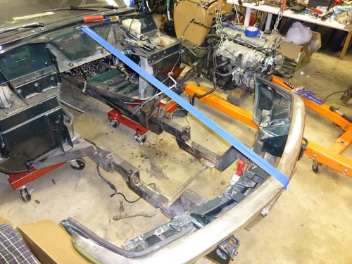
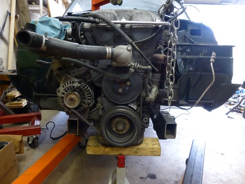
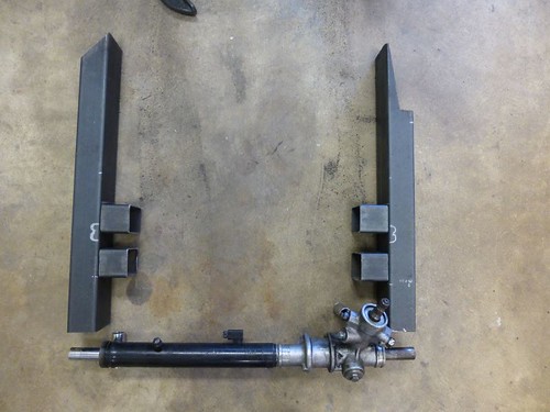
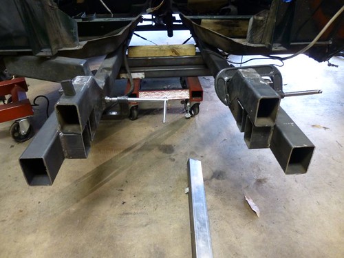
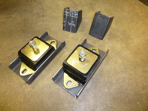
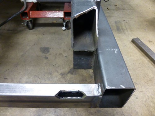
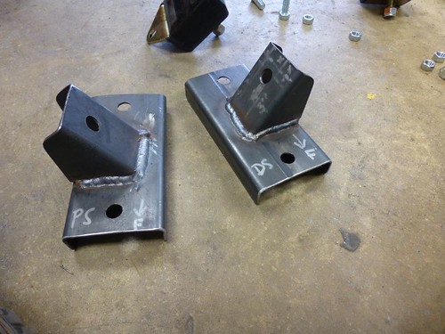
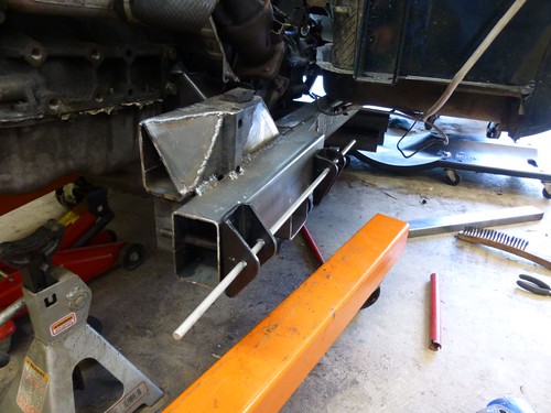
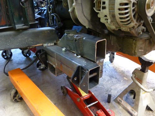
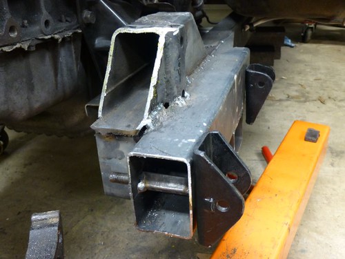
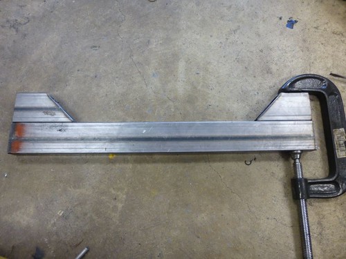
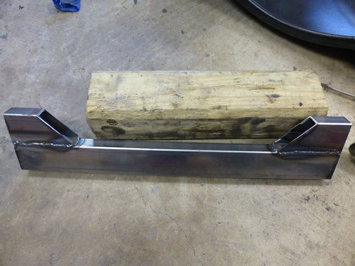
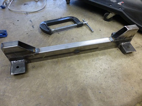
Completed the motor mount adapters.

I had to grind off a little from the angled portion of the adapter, bringing it to 55 degrees (from 60), in order for the mount to be at a right angle to the chassis. Not sure where the difference was (I measured the Miata motor mount brackets at 30 degrees), but both sides needed 5 degrees removed.
Image

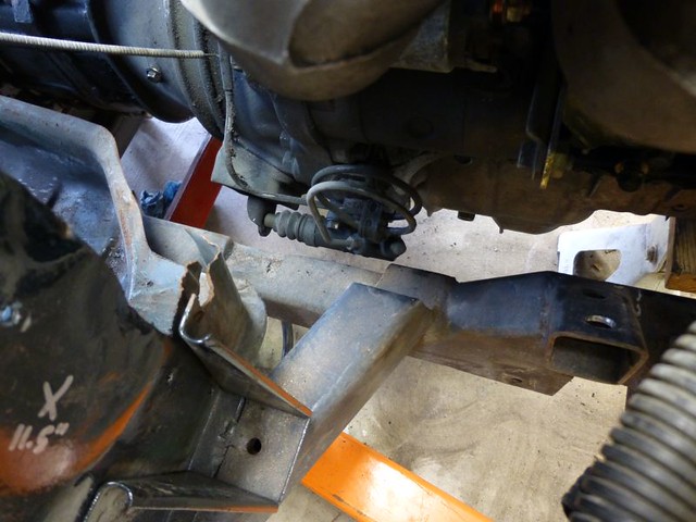
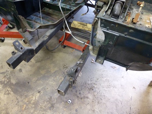
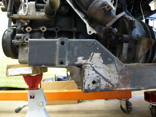
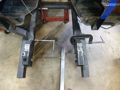
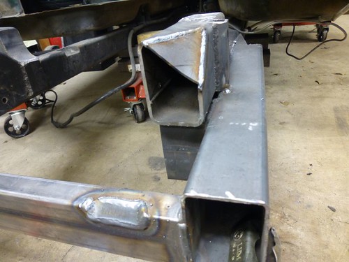
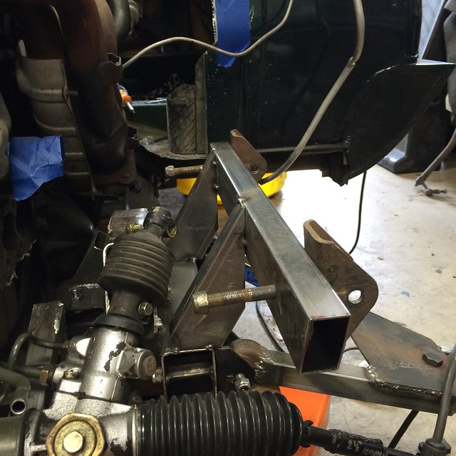
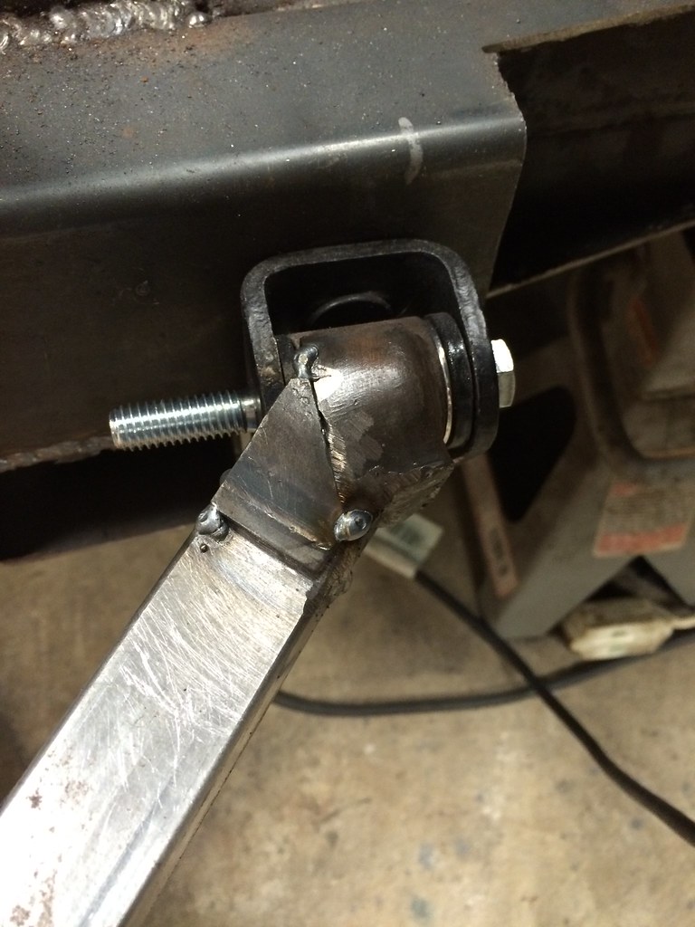
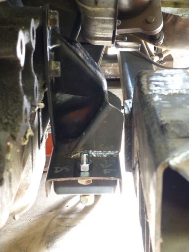
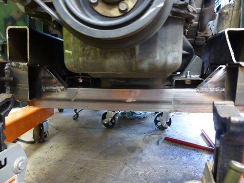
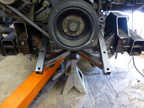
Driver's side clearance. I'll need to grind down that plate on the old chassis to give me a little more room. It no longer serves a purpose anyway since I removed the outrigger it was supporting.
Image

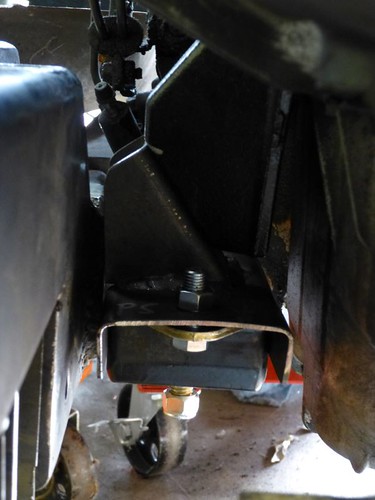
Passenger's side. There's about the same amount of clearance as on the driver's side, even though the camera angle doesn't show it.
Image

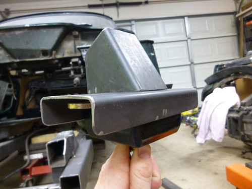
I'm going to drop the engine a little lower in the chassis to get it totally level and make the chassis brackets for the motor mounts easy peasy. Unfortunately, that also means I'll probably have to notch a good portion of the steering rack support so that the oil plan clears it. The upside is that this car is going to have awesome Ackerman -- the opposite of how the Spitfire was originally built [img]/media/img/icons/smilies/cool-18.png" class="smiley" alt="" />

As requested, much more wire burned this morning. But first, let me back up a little bit. As I mentioned earlier, I've been using the Wishbone suspension analyzer to try and design/optimize my suspension geometry virtually, prior to building it. After I got some good numbers, I realized that my steering rack had to move MUCH closer to the driver/engine/Front LCA bracket. This involved cutting out the nice crossmember I welded in earlier, as well as making the frame notch even larger. Done!

Except that I still wasn't able to get the rack as far back as I wanted, because I wanted that "ideal geometry" I had worked so hard for in Wishbone. *sigh* Moving the rack further back to achieve it would mean that the engine would have to go back further, which would push the shifter back further. The shifter is already at the point where I will probably have to cut and angle it, and I don't really want to construct a remote shifter. Plus, pushing everything back would increase the severity of my driveshaft u-joint angles, which are already approaching "questionable."

Enter design paralysis, the silent killer of major automotive projects.

Then, the ghosts of rallies past inspired me to say "berkeley it," live with "good enough." and press on.

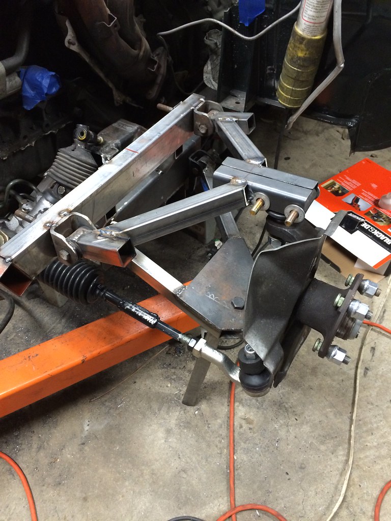
The rack will sit about 1" ahead of the tie rod ends instead of 0.4" behind them; however, due to the Miata spindle geometry I will still have positive Ackerman! Nice for the street, fairly inconsequential in the dirt.

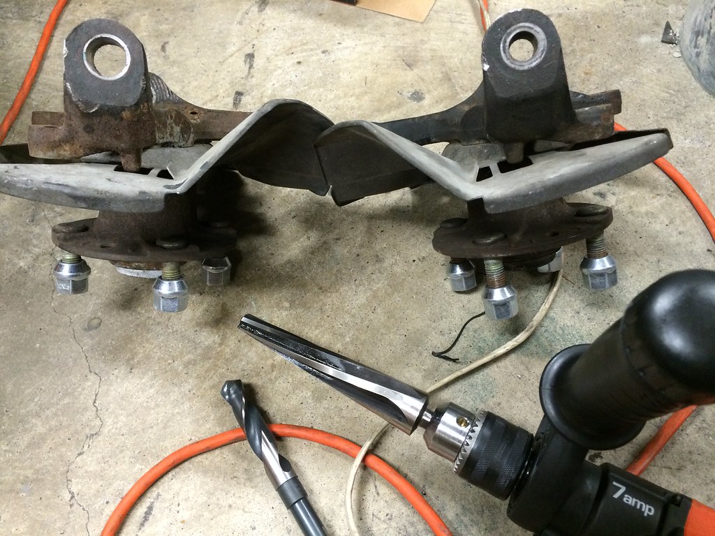
I also decided to use the Spitfire's bolt-in control arm bracket design; this will allow me to adjust camber with shims if needed, just like in the Spitfire, and it will keep me from worrying about my bracket welds failing due to poor penetration (those brackets are THICK... you'd think the Spitfire weighs 5000 lbs).

Image
Image


P.S. Cobalt drill bits are awesome, and worth the price IMO . They cut mild steel like buttah.

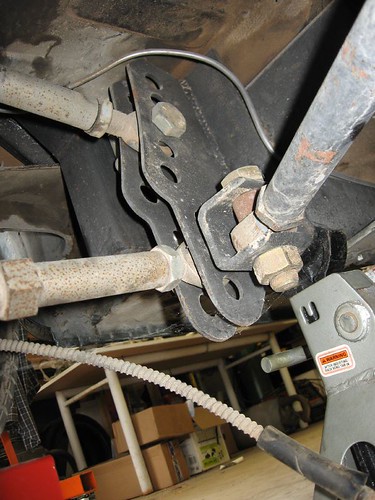
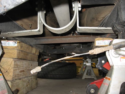
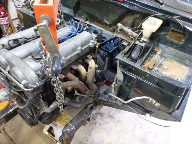
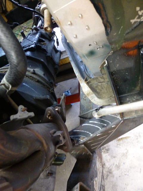
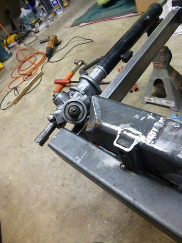
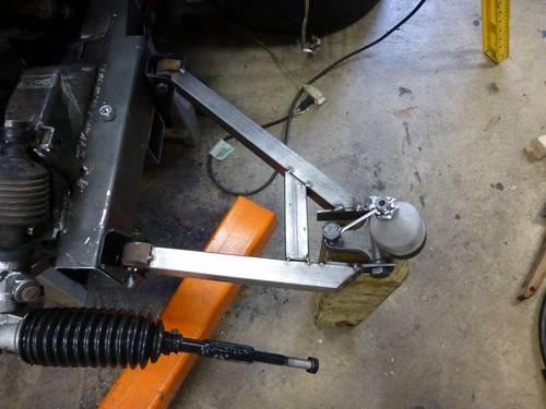
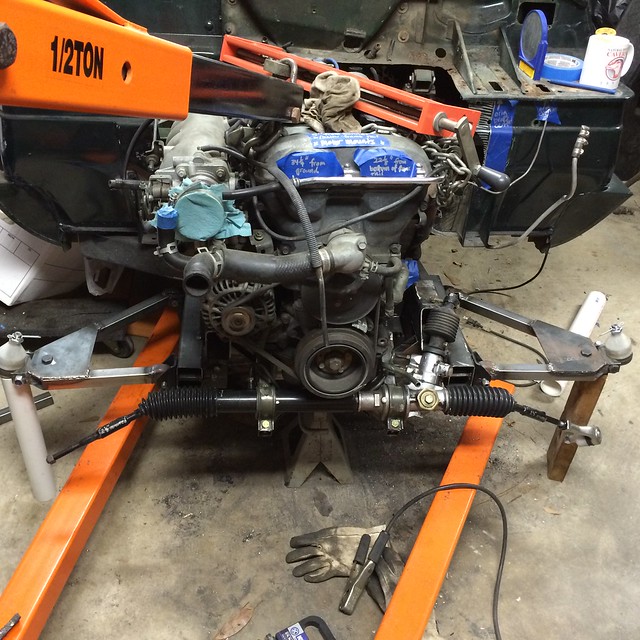
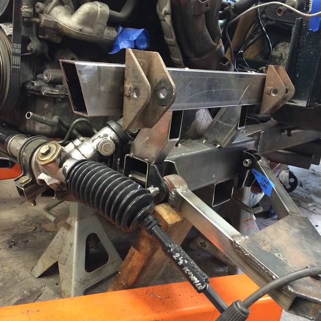
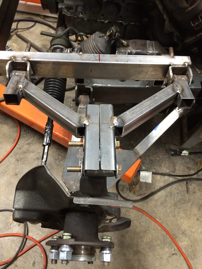
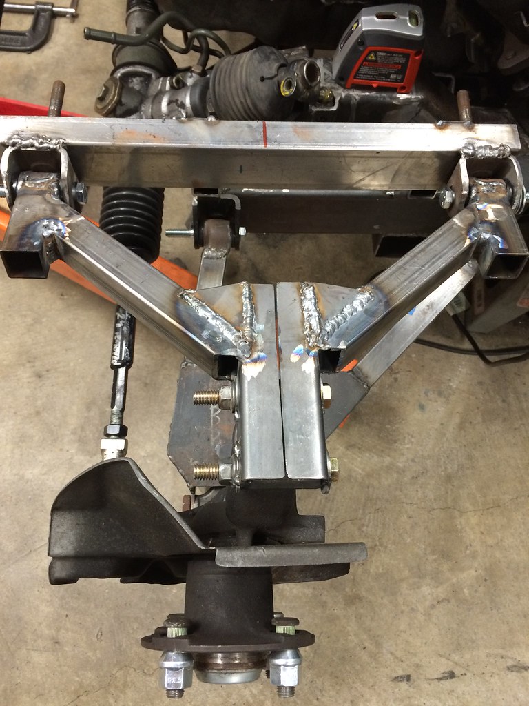
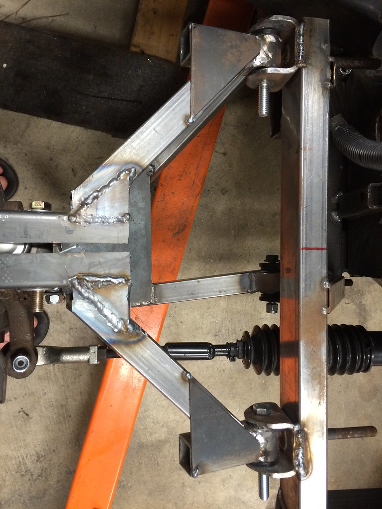
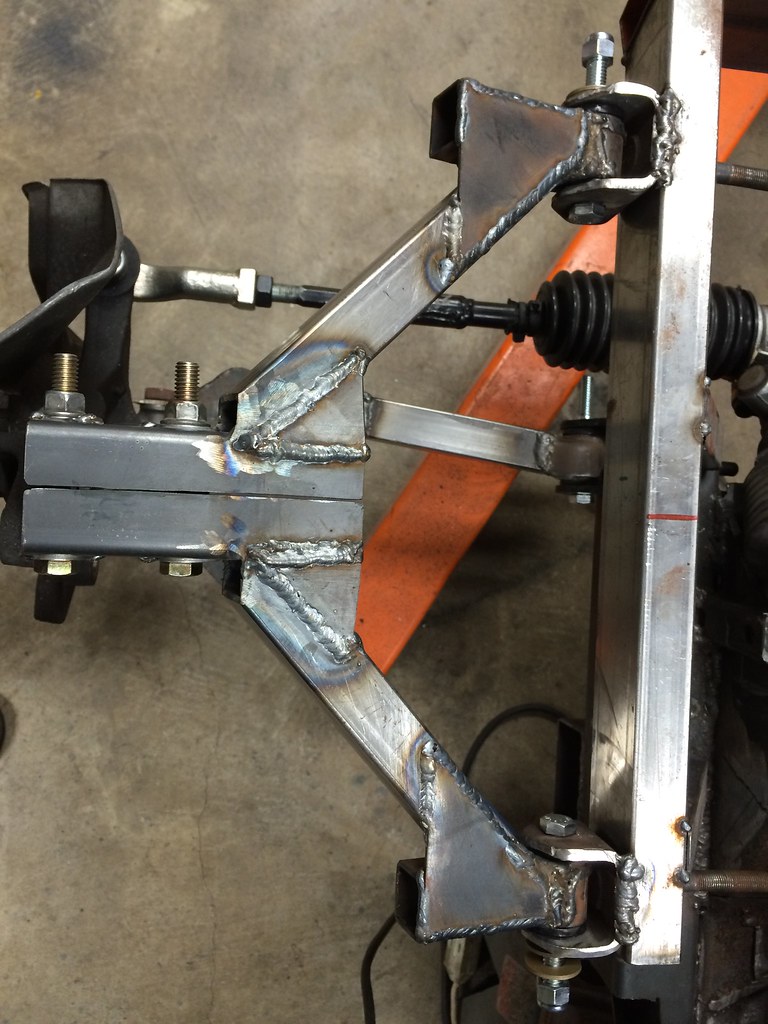
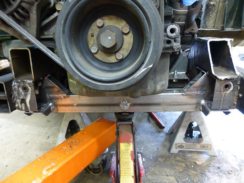
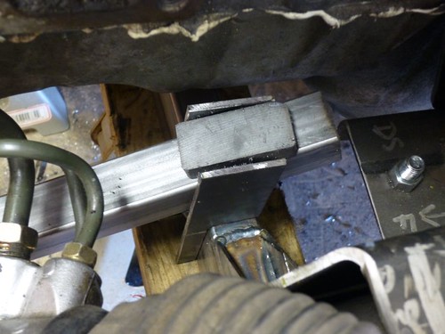
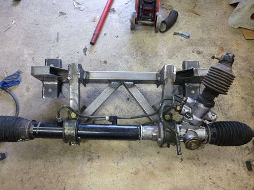
Well, it seems that I got lucky (that's what she said). The 5 degrees of "nose up" engine tilt created *just* enough room underneath the oil pan for me to slide the rack a little further back. Now the inner tie rod ends are positioned where I originally wanted them. Sometimes it's better to be lucky than good.

Image

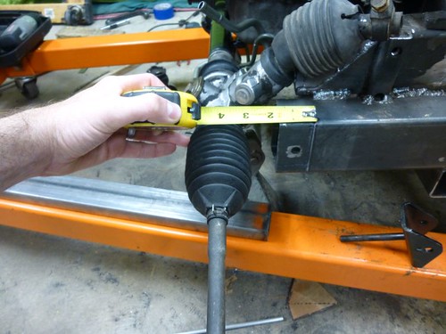
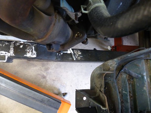
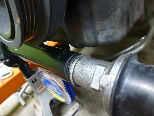
There's about 1/4" of clearance between that bump on the oil pan and the rack body. I think that should be enough with my urethane motor mounts, but if it looks like it might become an issue I can add some spacers to raise the engine.
Image

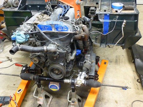
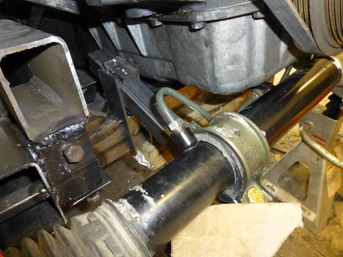
It did require even further trimming of the old chassis rail, so that the pinion has room. This is the third time I've trimmed this part. You can also see one of the spacers that I added at erohslc's prompting.

Image

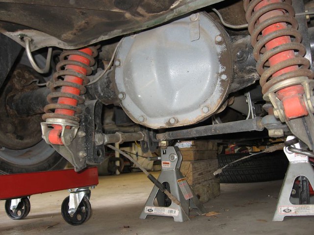
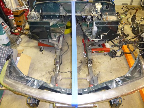
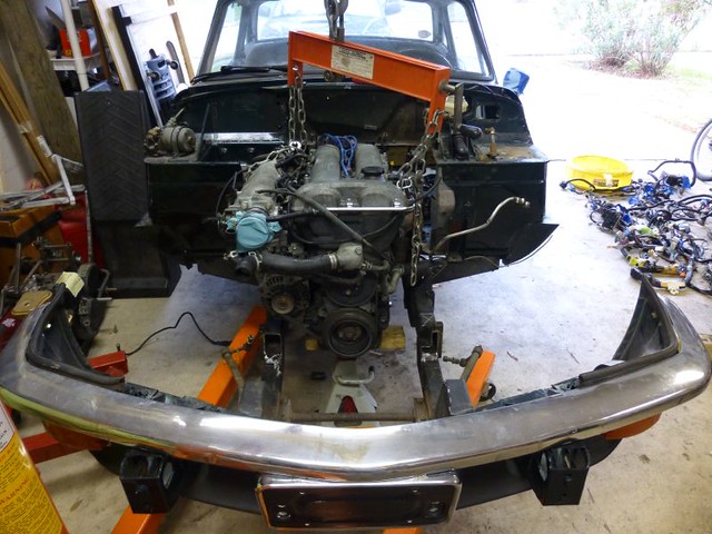
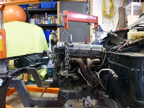
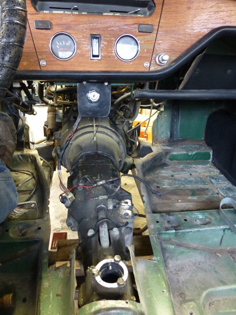
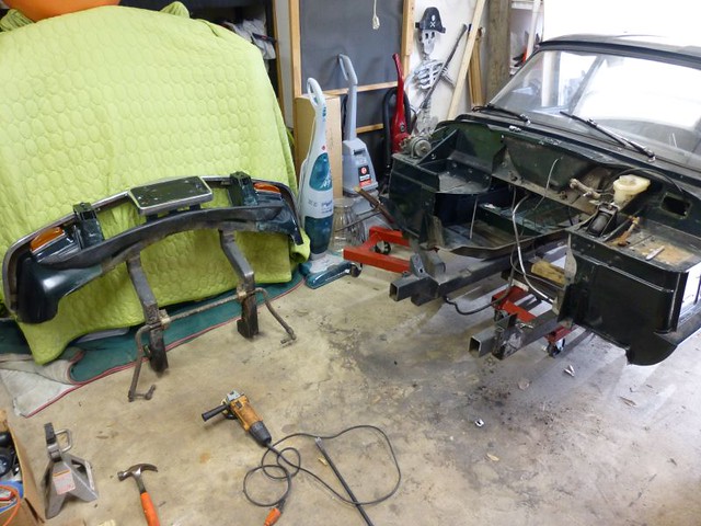
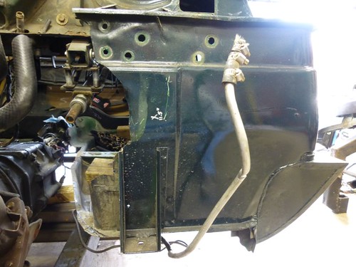
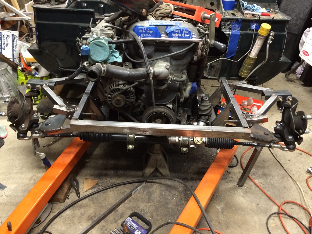
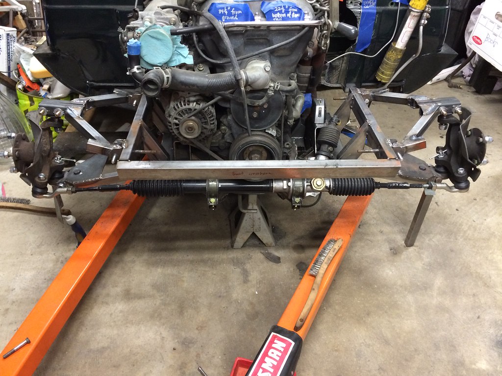
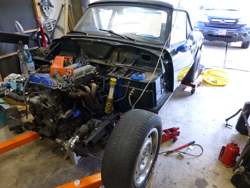
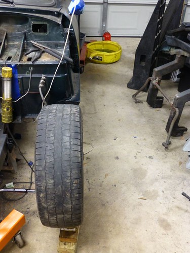
And a wide-angle view of the current state of things.
Image

Next up:

1. Steering rack crossmember
2. Upper suspension structure

Between karate tournaments, company outings, and kids' birthday parties, I haven't had much of a chance to melt metal during the past couple of weeks. However, I've been at the drawing boards when I got the chance, and this morning finally got the opportunity to crank out the beginnings of the steering rack crossmember.

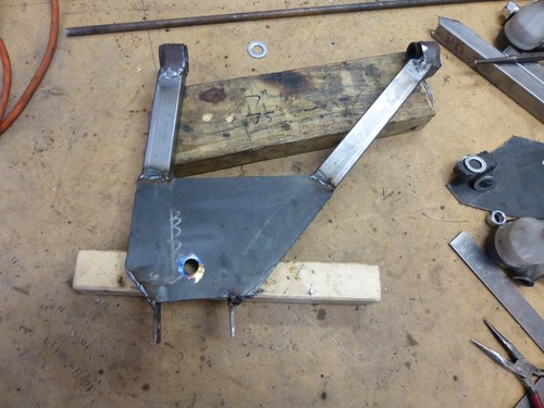
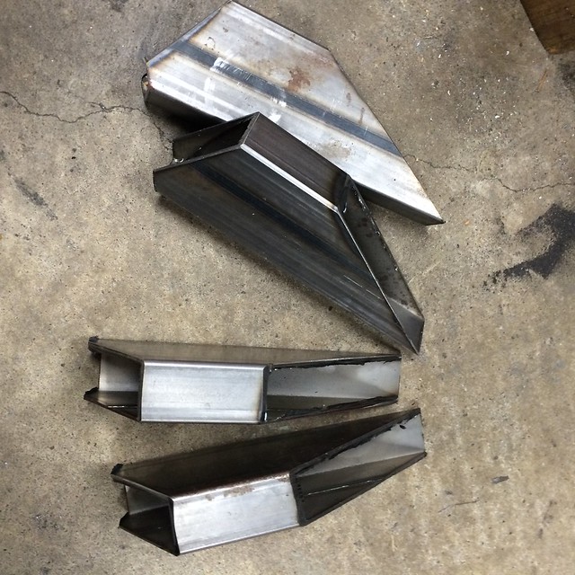
First, we'll start with some 1"x2" 16swg tubing. A few slices with the chop saw, and we're underway:
Image

Some passes with the trusty Weld-pak 100, and the pieces are joined.
Image

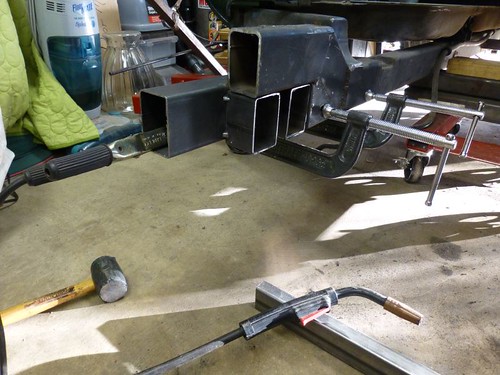
For those of you scoring at home, this is where this piece goes:
Image

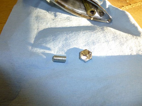
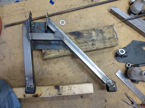
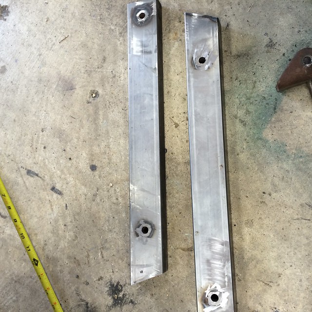
I could just weld the crossmember in place, but I want to be able to drop the oil pan (if needed) without pulling the engine. I'm going to bolt this piece in two planes, parallel to the drivetrain as well as vertically. Those vertical bolts will need these:
Image

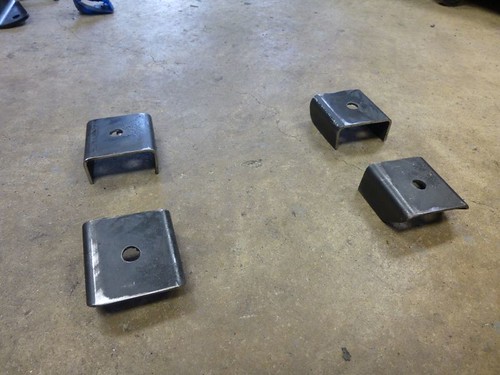
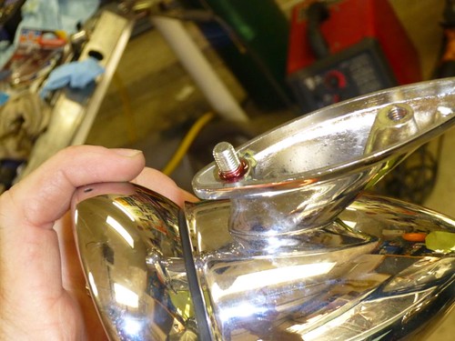
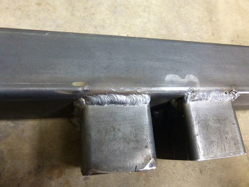
And now they're welded in place.
Image

The crossmember is then placed so that I can drill the holes for the other bolts. I'll say it again, cobalt drill bits are so nice compared to the cheap stuff.
Image

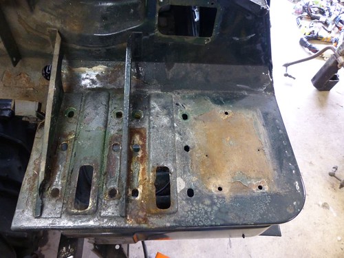
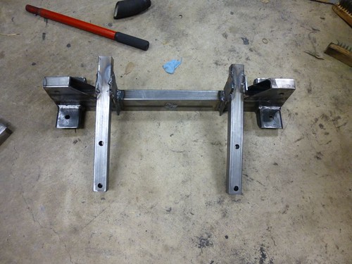
Here is the piece removed again, so that you can see the holes.
Image

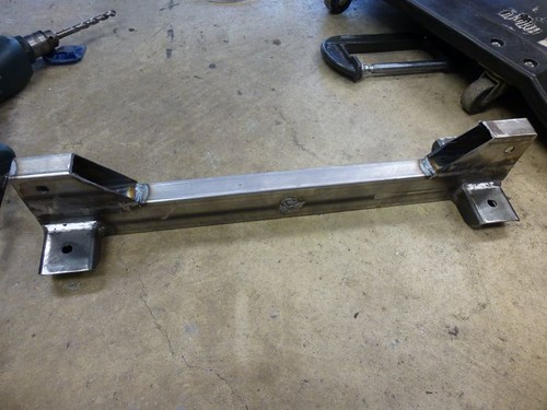
That's where we'll pause for now. Next up: getting the actual steering rack mounts fabricated and attached to the crossmember.
Image

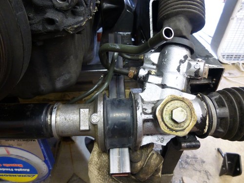
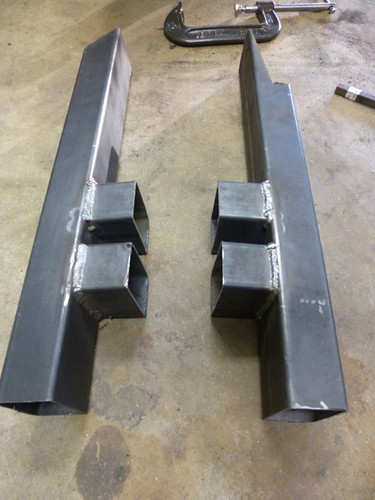
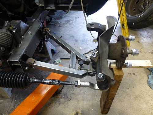
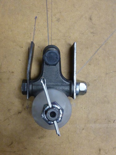
I've been working (here and there) on the steering rack crossmember during the past couple of weeks, and finally finished it yesterday. Started with a pair of these for each side:

Image

Mocking them up like so:
Image
Image

Then there was a bunch of fiddling around to make sure that the rack positioning was correct. Then welding happened:
Image

Image
Image

Then I bolted the rack in so that I could see just how wide my track was.
Image

Image
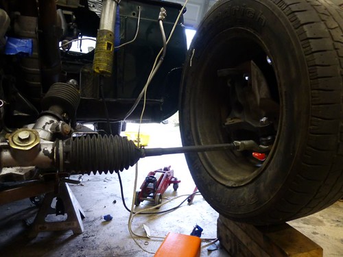
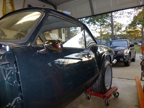
Pretty wide. Around 2" on each side, give or take. Damn, I guess I'll have to shorten the tie rods after all. You can see just how far it sticks out past the widest part of the body in this shot:
Image

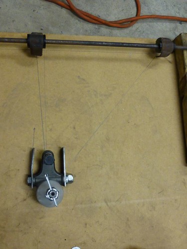
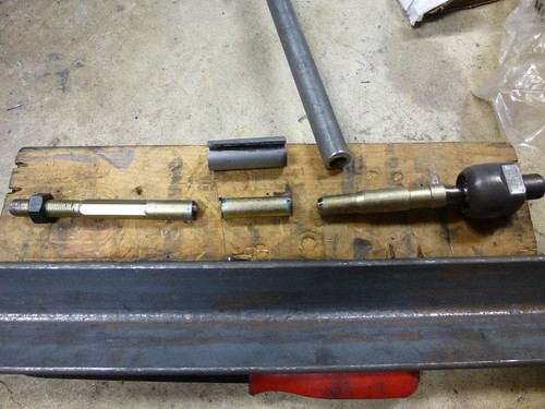
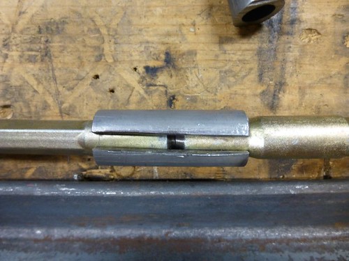
When we last left our hero, the Spitfire's track was about 2" too wide on each side. So, the next order of business was to correct that. I took 2 1/8" out of each tie rod, then beveled the edges for butt welding. I purchased a small length of DOM tubing with ID slightly *smaller* (0.51") than the OD of the tie rod (0.55"). I then split it lengthwise and pried it open slightly such that it would fit snugly over the tie rod pieces. This would give me more weld area for increased peace of mind.

Image
Image
Image

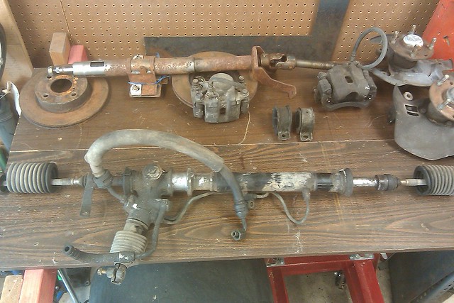
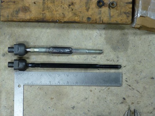
New tie rod vs. stock length tie rod:
Image

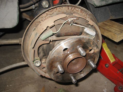
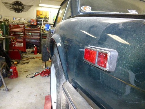
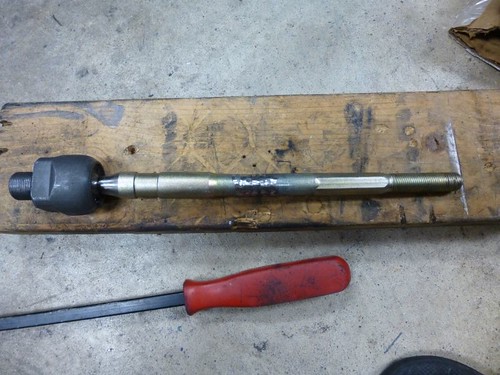
This was then repeated for the other side, and the new tie rods and boots were installed. Time to re-fit the wheel to check my work (*crosses fingers*).
Image
Looks good!

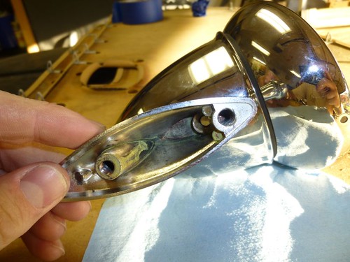
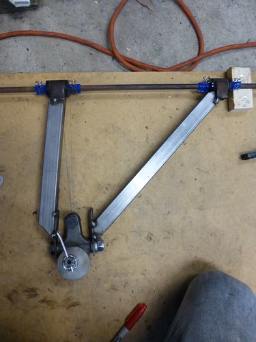
Now to start on the control arms. First, the driver's LCA. Step one, harvest bushing carriers (FYI, these control arms were a bit twisted, so it's not like I hacked up good parts).
Image

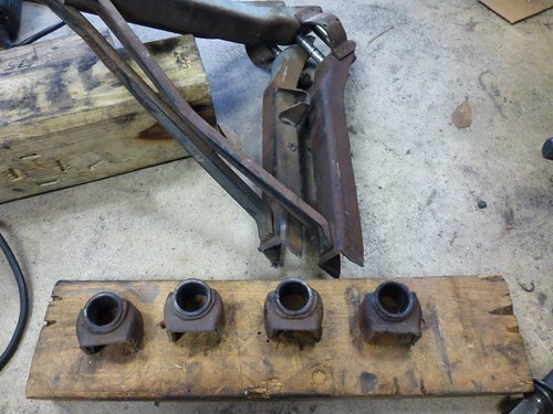
Now to begin making the bracket that holds the Miata lower ball joint. First, I cut a couple 1"x3" tabs out of 11 ga. sheet (first drilling the bolt holes and then reaming them out to 12mm because I didn't have a bit that size):
Image

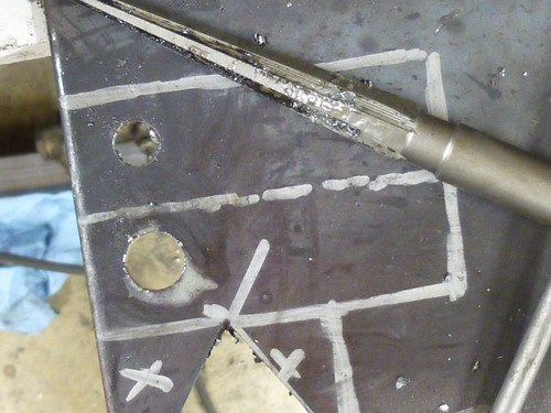
Tabs drilled and cut:
Image

The tab for the leading side has to be angled in order for the (future) tube to meet up with the bushing carrier:
Image

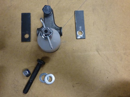
Here's the beginnings of my mockup. I have the urethane bushings in the carriers with some 3/8" rod threaded through. Next step is to fix the rod and carriers in place so that I can keep them steady enough to cut accurate tubes. Stay tuned!
Image

_________________
My Mazda BP-powered Triumph Spitfire project: http://grassrootsmotorsports.com/forum/build-projects-and-project-cars/1976-triumph-spitfire-50-v8-miata-18/54640/page1/


Last edited by Winston on July 21, 2015, 1:50 pm, edited 2 times in total.

Top
 Profile  
Reply with quote  
PostPosted: July 20, 2015, 1:18 pm 
Offline
User avatar

Joined: August 10, 2007, 4:38 pm
Posts: 217
Location: Houston, TX
This morning's work:

Aft leg measured, cut, and tacked in.
Image

Shock support tube cut and tacked in. Now to see if this crazy thing even fits the car.
Image

Success! Okay, now I can't help myself.

Image

This feels pretty good. Now for the top plate. Cut from the same 11 ga. sheet, it's pretty beefy.
Image

Underside.
Image

Whew! One side done. That only took... 5 hours?! Well, to be fair I was cutting the mirror image tubes and plate for the other side at the same time. Undoubtedly that one will go much more quickly.

Well, it's been almost a year and half since my last update. What have I been doing this whole time?

Mostly just polishing my knob.

Before:Image
After:Image

Oh, and the e-brake handle as well:
Image
Into:Image

Also received a lovely Nardi (knock-off?) wheel from my lovely bride for our anniversary this past year:Image

And this weekend I finally knocked out the passenger side lower A-arm:
Image
Image


<blockquote>kiwipete wrote:
Winston,I'm new to this commenting but just a inquiry.Why did you cut and weld your tierod when you can just grind down the rod ie;round off the hex on the rod ,thread the rod further along and cut off the excess.I have just done this on mineThis would be much safer and stronger.In New Zealand we are not allowed to cut and weld steering parts.
</blockquote>
Pete (if you're still around), that is probably the easiest and smartest way. I don't have the proper set of dies to cut the Miata thread. However, I'm confident in my cut/weld job. When it comes time to replace these tie rods, I'll order the die and shorten them as you describe.

EDIT: Sorry for the giant pics. Flickr has changed their site in the last year and a half, and I wasn't able to find the links to the reduced sizes... I'll work on that.

Time to work on the rest of the suspension.

First, some maths (yes, I know that the two angles are complementary, but calculating both allowed me to check my work)...
Image

First to cut the vertical pieces for the upper control arm support structure:
Image

Anti-crush inserts/guides for the control arm brackets (using the stock Spitfire brackets since I have them):
Image

Welded in:
Image

Ground down:
Image

Structure tacked in place with brackets:
Image
Image

I actually screwed up a little bit and accidentally made the bracket mounting holes 13" apart instead of the planned 14"; however, since I haven't yet made the upper control arms, it's no big deal. I just need to re-dimension them.

The structure extends forward past the front of the engine, and will allow me to tie the two sides together with a crossbar. The crossbar will also provide a jumping-off point for the bodywork/bumper support structure that will give the bonnet and radiator (and probably an anti-roll bar at some point) a place to sit.

The build continues to plod along slowly. Actually, I usually work on it in bursts, then nothing for a while... as you can probably tell. At any rate, I've been pushing myself to finish up the suspension. I think that if the front end looks more like a car instead of a Cessna with the cowl off, it'll motivate me to keep pushing forward.

I took a big, scary step and drilled my Miata spindles to accept the TR6 upper ball joint. The initial bore-out was done with a 5/8" bit, then finished with a 7 degree taper reamer to match the ball joint. It only took me three spindles to end up with two usable ones! After doing a decent job with the passenger spindle on my first try, I got a little cocky on the first driver's spindle and ended up drilling at an angle. I couldn't save it with the reamer (because I didn't notice quickly enough), and had to order another spindle off of eBay. This time I took a lot of extra time to make sure that I was drilling straight, and it turned out great. Here's the passenger's spindle, along with the implements of destruction, and the first driver's spindle (pre-botch job):
Image

Then I got to work on the upper A-arms. I cut and split some 2x3 steel tube and drilled the requisite holes to make the two sides of the ball joint cradle. I re-used the bushing carriers (as with the lower a-arms) and cut steel tube to mate them all up. I'll be adding a little plate at each joint to increase strength, but you get the idea:
Image
Image

Both sides near complete. Also, you can see the cross-member I added.
Image

I happened to look at the data tag in the Spit's door jamb the other day, and noticed that my car was built in May of 1976. So, in about 42 weeks, my car will turn 40. I think that getting it on the road by then (not "finished," just tagged and inspected) is a reasonably achievable goal. To keep me honest (and provide a little extra motivation), I'm going to provide weekly updates on my progress, typically posted Sunday or Monday. Without further ado:

<strong>42 weeks remaining.</strong>

I'm continuing to make the push toward sitting the car on four wheels, which involves making sure all of the suspension is strong/fully welded. I reinforced both upper A-arms at the ball joint end.

Image

Fully welded, just missing reinforcing plates at the bushing end and they'll be totally done.
Image
Image

I also picked up some extra 3/8" a-arm-to-chassis bolts from the hardware store, since I only had enough to do one side (I'm using two sets of Spitfire lower a-arm brackets to get all eight brackets). I'm basically ready to order my coilovers, since I'd really like to have them in hand for reference when building the mounts. I'm probably going to order from Viking Performance. Anyone have anything good/bad to say about them?

http://www.vi-king.com/

<strong>41 weeks remaining.</strong>

I spent most of my garage time this week/weekend in cleaning mode. Though that means that not much got done on the car itself, the upside is that it will make it easier to work on it.

I finished up the upper a-arms with another set of gussets, and that's basically all that got done other than some staring and thinking, measuring and planning.

Image
Image

I also added some small gussets on the lower a-arms.
Image

I'm still undecided about whether or not to further reinforce the rear tube of the lower a-arms. It carries basically all of the loads introduced into the lower arm. I was thinking of "half-sleeving" it by splitting some 16swg square tubing into two L-channels, then welding those onto the existing 16swg tubes. Anybody have any thoughts about this?

There won't be any progress the next two weeks, nor an update on 7/27 since we're flying to London on Friday for vacation. I don't see my housesitters (in-laws) doing any work on the car while we're gone :) Maybe I'll have some pictures from the Lotus factory (doubtful, pictures are forbidden) or classic Team Lotus workshop (likely) for the 8/3 update.

_________________
My Mazda BP-powered Triumph Spitfire project: http://grassrootsmotorsports.com/forum/build-projects-and-project-cars/1976-triumph-spitfire-50-v8-miata-18/54640/page1/


Last edited by Winston on July 21, 2015, 1:51 pm, edited 2 times in total.

Top
 Profile  
Reply with quote  
PostPosted: July 20, 2015, 1:22 pm 
Offline

Joined: August 19, 2014, 5:17 pm
Posts: 685
Location: England
Cant see any of the pics Winston so it never happened :boxing: :lol:


Bob

_________________
Build Log viewtopic.php?f=35&t=16640&p=187700#p187700

Mancave http://s1116.photobucket.com/user/mypic ... ow/mancave


Top
 Profile  
Reply with quote  
PostPosted: July 20, 2015, 1:28 pm 
Offline
User avatar

Joined: August 10, 2007, 4:38 pm
Posts: 217
Location: Houston, TX
Lol, yep... they should all be fixed now :)

_________________
My Mazda BP-powered Triumph Spitfire project: http://grassrootsmotorsports.com/forum/build-projects-and-project-cars/1976-triumph-spitfire-50-v8-miata-18/54640/page1/


Top
 Profile  
Reply with quote  
PostPosted: July 20, 2015, 3:35 pm 
Offline

Joined: August 19, 2014, 5:17 pm
Posts: 685
Location: England
Winston your welder is worrying me what is it?

Bob

_________________
Build Log viewtopic.php?f=35&t=16640&p=187700#p187700

Mancave http://s1116.photobucket.com/user/mypic ... ow/mancave


Top
 Profile  
Reply with quote  
PostPosted: July 20, 2015, 4:15 pm 
Offline
User avatar

Joined: August 10, 2007, 4:38 pm
Posts: 217
Location: Houston, TX
It's a Lincoln Weld-Pak 100 (iirc) MIG. Also please ignore those suspension bracket welds, my MIG wire was running out and became erratic. They will be ground off and re-welded.

_________________
My Mazda BP-powered Triumph Spitfire project: http://grassrootsmotorsports.com/forum/build-projects-and-project-cars/1976-triumph-spitfire-50-v8-miata-18/54640/page1/


Top
 Profile  
Reply with quote  
PostPosted: July 21, 2015, 12:51 pm 
Offline
User avatar

Joined: June 12, 2012, 8:40 pm
Posts: 472
Location: Mount Airy, NC
I'm kinda surprised that there wasn't a bigger response to this thread. Maybe its because everyone is either moving or on vacation. I think it's a great idea and will be watching your progress.

_________________
My car viewtopic.php?f=37&t=16434
1930s Style Sports Car viewtopic.php?f=36&t=16888


Top
 Profile  
Reply with quote  
PostPosted: July 21, 2015, 1:09 pm 
Offline
User avatar

Joined: October 19, 2012, 9:25 pm
Posts: 3365
Location: Summerville, SC
Looks like fun

Waaaay back when I wanted to swap the big V Twin from my Honda Magna into one of my Spits. I never got around to it.

This should be fun to watch

_________________
Too much week, not enough weekend.

OOPS I did it again
http://www.locostusa.com/forums/viewtopic.php?f=35&t=17496

Blood Sweat and Beers
http://www.locostusa.com/forums/viewtopic.php?f=35&t=15216


Top
 Profile  
Reply with quote  
PostPosted: July 21, 2015, 1:35 pm 
Offline

Joined: August 12, 2012, 6:38 pm
Posts: 1937
Location: worcester county, Massachsetts
TooBusy wrote:
Looks like fun

Waaaay back when I wanted to swap the big V Four from my Honda Magna into one of my Spits. I never got around to it.

This should be fun to watch


fixed that for you ;-)

_________________
The B-3 build log: http://www.locostusa.com/forums/viewtopic.php?f=36&t=13941 unfortunately, all the pictures were lost in the massive server crash

The beginnings of the Jag Special,
https://www.locostusa.com/forums/viewtopic.php?f=36&t=19012
Again, all pictures were lost.


Top
 Profile  
Reply with quote  
PostPosted: July 21, 2015, 1:38 pm 
Offline
User avatar

Joined: October 19, 2012, 9:25 pm
Posts: 3365
Location: Summerville, SC
Doh!

:cheers:

_________________
Too much week, not enough weekend.

OOPS I did it again
http://www.locostusa.com/forums/viewtopic.php?f=35&t=17496

Blood Sweat and Beers
http://www.locostusa.com/forums/viewtopic.php?f=35&t=15216


Top
 Profile  
Reply with quote  
PostPosted: July 21, 2015, 1:49 pm 
Offline

Joined: August 19, 2014, 5:17 pm
Posts: 685
Location: England
I like the use of the square section on the bones,it makes the transition onto the associated brackets so much easier. :cheers:

bob

_________________
Build Log viewtopic.php?f=35&t=16640&p=187700#p187700

Mancave http://s1116.photobucket.com/user/mypic ... ow/mancave


Top
 Profile  
Reply with quote  
PostPosted: July 21, 2015, 1:58 pm 
Offline
User avatar

Joined: August 10, 2007, 4:38 pm
Posts: 217
Location: Houston, TX
Thanks for the positive response, guys. The square tube did make the wishbone fabrication much easier. I knew that I wanted bushings instead of rod ends, and the stock Spitfire brackets are made from c-channel, so it was just natural to use the square tube I already had laying around.

bob, which welds were you concerned about? The suspension bracket welds (which I agree need to be re-done)? I went back through the pics and didn't notice any others that looked bad to me, but I'm certainly open to feedback -- safety first!

_________________
My Mazda BP-powered Triumph Spitfire project: http://grassrootsmotorsports.com/forum/build-projects-and-project-cars/1976-triumph-spitfire-50-v8-miata-18/54640/page1/


Top
 Profile  
Reply with quote  
PostPosted: July 21, 2015, 3:11 pm 
Offline

Joined: August 19, 2014, 5:17 pm
Posts: 685
Location: England
Winston wrote:
bob, which welds were you concerned about? The suspension bracket welds (which I agree need to be re-done)? I went back through the pics and didn't notice any others that looked bad to me, but I'm certainly open to feedback -- safety first!


The welds look a bit cold, are you on gas or using the fluxed wire?

Image

_________________
Build Log viewtopic.php?f=35&t=16640&p=187700#p187700

Mancave http://s1116.photobucket.com/user/mypic ... ow/mancave


Top
 Profile  
Reply with quote  
Display posts from previous:  Sort by  
Post new topic Reply to topic  [ 26 posts ]  Go to page 1, 2  Next

All times are UTC - 5 hours [ DST ]


Who is online

Users browsing this forum: No registered users and 9 guests


You cannot post new topics in this forum
You cannot reply to topics in this forum
You cannot edit your posts in this forum
You cannot delete your posts in this forum
You cannot post attachments in this forum

Jump to:  
POWERED_BY