LocostUSA.com

Learning how to build Lotus Seven replicas...together!
It is currently April 16, 2024, 1:47 pm

All times are UTC - 5 hours [ DST ]


Post new topic Reply to topic  [ 118 posts ]  Go to page Previous  1, 2, 3, 4, 5, 6, 7, 8  Next
Author Message
 Post subject:
PostPosted: July 6, 2007, 1:52 am 
Offline
User avatar

Joined: July 29, 2006, 9:10 pm
Posts: 3163
Location: Oregon, usually
Thanks Dale, for the side protection clarification.

I'm back to the glassing part of the project. The blue waterbase Kilz paint (white with a pigment) didn't work out well, it clogged the sandpaper something horrid, so I sprayed it over with automotive primer (polyester, catalized) and that seems fine.

It's sanded now and ready for flanges, wax and PVA, plus I did similar to the two other patterns for this front fender project; the rear tapered section and a curved insert to blend the front and rear together.

Here's how folks had to visualize stuff before there was Photoshop and CAD. I've used green masking tape to show the outline, kinda, of what I think it'll look like when done.


You do not have the required permissions to view the files attached to this post.

_________________
Locost builder and adventurer, and founder (but no longer owner) of Kinetic Vehicles


Top
 Profile  
Reply with quote  
 Post subject:
PostPosted: July 6, 2007, 1:57 am 
Offline
User avatar

Joined: July 29, 2006, 9:10 pm
Posts: 3163
Location: Oregon, usually
That thing in the background of photos 41 and 45 above is the pattern to make a mold to make patterns for the fender extension. It'll probably make more sense when a couple parts come out of the mold; about a week from now I'd guess.


You do not have the required permissions to view the files attached to this post.

_________________
Locost builder and adventurer, and founder (but no longer owner) of Kinetic Vehicles


Top
 Profile  
Reply with quote  
 Post subject:
PostPosted: July 6, 2007, 9:11 am 
Offline
User avatar

Joined: September 22, 2005, 7:59 pm
Posts: 371
Jack, looks good so far. Just wondering if you going to have enough clearance there for turning the wheels on bump. I had a hell of a time trying to come up with close dimensions that allowed the wheels to turn lock to lock. Now I was using wider and taller wheels 195-65-15 on the front so that made it harder and around 45 degrees turning on the wheels as well. I found I had to go further back on the wheel opening and farther forward. Either way I did it, it changed the look.
Dale


Top
 Profile  
Reply with quote  
 Post subject:
PostPosted: July 6, 2007, 8:42 pm 
Offline
User avatar

Joined: July 29, 2006, 9:10 pm
Posts: 3163
Location: Oregon, usually
dale wrote:
Just wondering if you going to have enough clearance there for turning the wheels on bump.

Well, I'll have enough when I'm done. Clearence is just a sawcut away. I did find, though, that with the camber change in bump, the top of the wheel comes into the fender a bit (as seen from outside) and since the top of the wheel doesn't move very far as it pivots on the steering axis, I can get away with more fender there than I'd anticipated. So don't pay too much attention to the tape, the fender will get mounted with the spring removed from the shock, I'll check for clearence lock-to-lock through the full suspension travel range, and whittle where needed.

_________________
Locost builder and adventurer, and founder (but no longer owner) of Kinetic Vehicles


Top
 Profile  
Reply with quote  
 Post subject:
PostPosted: July 12, 2007, 10:35 am 
Offline
User avatar

Joined: July 29, 2006, 9:10 pm
Posts: 3163
Location: Oregon, usually
Forgot my camera back home...not that I could have taken any pix once things got sticky, but perhaps I'll get somebody to click the shutter for me on my next layup.

This mold is going to be in two parts; a left and right, split down the middle. That way I can make middle extension sections to make fenders of various widths...which is why the design is a simple curve (flat from side to side) at this stage.

The flanges around the perimeter help keep the mold rigid, and give me something to trim to when the parts are curing. The flange for the wheel cutout is made from two pieces of 1/2" MDF stacked together, for a 1" high flange. The flanges are covered with polyester packaging tape, so I didn't have to bother with painting and waxing and so forth.

The pattern itself did get painted and waxed and so forth...gray polyester primer, Partall green wax (three coats) and PVA (three coats). The resin is an isopthalic tooling resin; it's pricy and cures slowly but it doesn't shrink much. The fiberglass is a nondirectional mat; it's relatively inexpensive compared to cloth and there isn't any pattern print-through. The gel coat is a tooling black, the color is so I can see whatever I'm spraying on it when making parts (and it's unlikely I'll want any black parts--a tooling orange gel coat is available if you <want> to make black parts).

Once this first half of the mold has cured and the flanges trimmed, I'll lay up the other half. Probably this weekend.


You do not have the required permissions to view the files attached to this post.

_________________
Locost builder and adventurer, and founder (but no longer owner) of Kinetic Vehicles


Top
 Profile  
Reply with quote  
 Post subject:
PostPosted: October 19, 2007, 12:25 am 
Offline
User avatar

Joined: July 29, 2006, 9:10 pm
Posts: 3163
Location: Oregon, usually
Wow, three months since I've added anything. Part of the problem is it's hard to take photos while actually working in fiberglass 'cause it'll make the camera sticky. Other prob is, there's been a lot going on.

So here's how the other half of the mold was made.

After the first half cured, I removed it from the pattern, cleaned, sealed and coated it with Chem Trend brand Cleaner EZ, Sealer EZ, and Chemlease 2182. These products are much easier to use than green wax and PVA--one coat of cleaner, three coats each of the sealer and release, you just wipe them on, wipe them off, and give them 45 minutes to dry--but they only work on polyester resins (of which gelcoat is an example) so they're not much use when making patterns out of MDF or body putty or plaster. Then I unscrewed the wheel cutout flange from the left side of the pattern, flipped it over and screwed it onto the right side of the pattern, recoated the pattern with three new coats of PVA and put the pattern back in the first half mold.

The second half of the mold was elcoated and laid up like the first half, except I used vinylester resin, which I had on hand for an unrelated carbon fiber project, and this particular vinylester is enough stiffer than the isothalic used in the first half that I didn't bother with a couple of the flanges and the coremat. Besides, this mold isn't going to be a production mold. This is a mold for making patterns which will be used for the production molds.

Why go to all this trouble? 'Cause the left and right fender patterns will be slightly different from each other, as will patterns for diferent tire sizes, and patternmaking from scratch is a huge chore compared to popping rough patterns out of a mold and tweaking them to suit. It might take me a couple/few tries to get the wheel cutout right, for example, and blending the front section of the fender to its trailing section will be some work and may call for a do-over...all in all, I normally go through an iteration or three before I'm ready for production, and so I make interim molds. It's kinda like hitting 'save' in photoshop, even if you aren't actually finished yet.

The big cardboard box was used as a curing oven; I put an electric heater in with them and set the temp to 80 degrees (degrees F. for polyester, though with epoxies we do C. for post-cure).


You do not have the required permissions to view the files attached to this post.

_________________
Locost builder and adventurer, and founder (but no longer owner) of Kinetic Vehicles


Top
 Profile  
Reply with quote  
 Post subject:
PostPosted: October 19, 2007, 7:20 am 
Offline
User avatar

Joined: July 29, 2006, 9:10 pm
Posts: 3163
Location: Oregon, usually
Since this mold is a bit quick-and-dirty, I took advantage of one of the...you know how in software a 'bug' can be described as an 'undocumented feature'?... I took advantage of one of the undocumented features of using polyester packing tape as a release: the volatiles in gelcoat (or other polyester resin) make the tape swell and wrinkle and ripple a little bit. Anyway, by using that tape as a release for the joining flange when building the left half of the mold, the flange got a wrinkleripple surface which provided an alignment pattern for the right half of the mold.

So...you know the drill; after it had fully cured, the new mold hald was cleaned, sealed and released as previously explained (or it could have been surfaced with a mold release wax, or Partall and PVA, or whatever suits one's fancy and preferences). Then the halves were placed face-to-face and the flanges clamped together with spring clamps (the halves fell neatly into alignment thanks to the wrinkleripples) and a row of 1/4" holes drilled through both flanges. The flanges were bolted together with 1/4" bolts and wingnuts, and they were ready for a part to be gelcoated and laminated inside the mold. Ta-dah! The mold is done, and if I were making a one-off car, this is where I'd stop working on the mold; I'd just pull a couple parts from it and hand trim (and hand fit) each part to fit each side.

The mold for the trailing section of the fender was made roughly the same way.

Now then, this is the bodymakers' version of when a Locost builder gets his chassis on its wheels for the first time, and sits in it and makes motor noises: here are the first parts out of the molds, not even trimmed yet, just clamped to the chassis with spring clamps. I think it's gonna look cool.


You do not have the required permissions to view the files attached to this post.

_________________
Locost builder and adventurer, and founder (but no longer owner) of Kinetic Vehicles


Last edited by JackMcCornack on October 19, 2007, 10:24 am, edited 1 time in total.

Top
 Profile  
Reply with quote  
 Post subject:
PostPosted: October 19, 2007, 9:54 am 
Offline
User avatar

Joined: July 29, 2006, 9:10 pm
Posts: 3163
Location: Oregon, usually
My friends, I have an aesthetic question.

Looking at the pix above, I'm thinking, "hmm...maybe the bottom of the rear of the fender shouldn't be trimmed level after all...there's still plenty of area beneath it to let the cooling air out...and it gives it a bit more of the old fashioned look; more pontoony and less the look of a 21st century LMP...I wonder..."

So since the next major body bit is the exit duct that fits under the fender, this is a good time to decide. Comments, please?

_________________
Locost builder and adventurer, and founder (but no longer owner) of Kinetic Vehicles


Top
 Profile  
Reply with quote  
 Post subject:
PostPosted: October 19, 2007, 10:54 am 
Offline

Joined: August 15, 2005, 10:13 pm
Posts: 7043
Location: Charleston, WV
I think it would look good as long as there was a panel under it to blend the pontoon into the chassis.


You do not have the required permissions to view the files attached to this post.

_________________
He is a wise man who does not grieve for the things which he has not, but rejoices for those which he has.


Top
 Profile  
Reply with quote  
 Post subject:
PostPosted: October 19, 2007, 11:44 am 
Offline
User avatar

Joined: July 29, 2006, 9:10 pm
Posts: 3163
Location: Oregon, usually
chetcpo wrote:
I think it would look good as long as there was a panel under it to blend the pontoon into the chassis.

My intention is an S-shaped panel/duct that'll let the air out from the radiator flow smoothly along the side of the car. I hope that written description is sufficient, 'cause I'm not good at drawing S-shaped panels. :-)

If the front of the pontoon were left blunt, it wouldn't do much for streamlining...the car might be as draggy as the traditional Se7en shape. Well, okay, not that draggy, but pretty dang draggy, I'll tell ya.

_________________
Locost builder and adventurer, and founder (but no longer owner) of Kinetic Vehicles


Top
 Profile  
Reply with quote  
 Post subject:
PostPosted: October 19, 2007, 7:49 pm 
Offline
User avatar

Joined: September 22, 2005, 7:59 pm
Posts: 371
Looking good Jack. I know that part behind the wheel is hard to get looking nice. What if you had a straight panel down from behind the wheel just as trim to follow the wheel well line and from the bottom of that straight to the bottom of your pontoon. Then have your "S" shaped pannel duct out right behind it. The trim piece may only have to be a few inches in lenth (front to back)


You do not have the required permissions to view the files attached to this post.


Top
 Profile  
Reply with quote  
 Post subject: Full body side pods
PostPosted: October 24, 2007, 9:10 pm 
Offline

Joined: January 22, 2007, 5:13 pm
Posts: 313
Location: Anchorage Alaska
Looking good!

I was just browsing thru the lowcost website and looked at the thread on HARDTOPs for the Sevens.

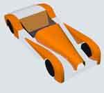
Your body design is very similar to the Donkervoort hardtop race car. And it is very nice too!

Seeing the photos of the Donkervoort with full side pods and hardtop (with a wing too!) opened my mind up to exciting possibilities for my next project.

I'm not keen on the 7 style nor the non existent side impact protection of the basic design. But by building side pods with structural tubes hidden in it, mostly just the upper surface, would really make the car safer. Then by building a nice rollcage it would be the structure for the hardtop.

Which got me thinking of the ultralight boat building technique of using heat shrink (aircraft) Dacron to make the roof and side pod coverings out of. Next to no weight added, relatively inexpensive, easy to use, easy to fix, easy to paint. The car would need fiberglass or metal fenders because of the rock impact strength required, and the hood due to engine heat, but the roof, side pods, rear end, and perhaps the nose could all be Dacron.

No, it would not be removable, although I am thinking of how that could be done too, with a perimeter frame that the Dacron is attached to that is bolted to the car frame, depends on how flexible the paint is I think. But once the car is sorted out, how often do you take all the body panels off?

My mind raced on to the tail end of the 7 that I have never liked, the trunk. So I would stretch it out to a point like the Bugatti T35 (T37, T39?) but have the roof (Roll cage) sweep back to the tail so that the side profile would be similar to the Bugatti Atlantic.

Doors could be simple bent Lexan Gull Wings that I would not even try to seal from water intrusion. Could be done, but a lot of extra work for a car that I would not choose to drive in the rain anyway. 8)

Inside the cockpit I would not cover the roll cage so that the inside of the Dacron covering would be exposed to reinforce the ultralight theme. This would require the roll cage to have very nice bends to get the roof line shape nice.

Anyhow, just some ideas (I'm full of 'em they tell me) :roll:


Top
 Profile  
Reply with quote  
 Post subject:
PostPosted: October 24, 2007, 10:10 pm 
Offline

Joined: August 16, 2005, 10:29 am
Posts: 1072
Location: Alberta, Canada
Going very well. Can't wait for the next installment.


Top
 Profile  
Reply with quote  
 Post subject:
PostPosted: October 26, 2007, 6:44 pm 
Offline
Databases fear me
User avatar

Joined: June 21, 2006, 7:02 pm
Posts: 890
Location: Lethbridge Alberta
looking really good.
Matches your avatar quite well.
But a Point if I may, now this is my personal taste nothing more, but I'd personally aim for amore of a traditional lotus 7 nosecone/rad opening than the narrow rounded opening of your avatar. but seriously, this will be a hot looker when done. Its got me thinking of doing a more enclosed body.

I've always wanted to to a Jag "C" type replica in aluminum.

_________________
Pictures of just a few of my projects


Top
 Profile  
Reply with quote  
 Post subject:
PostPosted: October 27, 2007, 1:47 am 
Offline
User avatar

Joined: July 29, 2006, 9:10 pm
Posts: 3163
Location: Oregon, usually
Violentblue, the avatar is taken from a Rhino file (my first Rhino file, in fact--I think I was still working off the 25-save demo version) where the nose is draped over that 1100cc Kubota diesel. The car under construction in this thread has a Miata powerplant, and will have a common enough Locost nose (a TTL nose, to use the Kinetic nomenclature) just trimmed on the bottom to fit the...what do you call that panel between the nose/bonnet and the fenders? Gosh, I'm going to have to make up some more patios, I guess.

Anyway, the main reason it matches the avatar is I used the avatar drawing to make the template for the fender profile. But this is the last part (knock wood) I'm making this way; this was mostly to show how body development can done low tech and low budget. I plan to make the rear fenders from my 3D foam printer (which ain't up and running yet), using Rhino with MadCAM to write the tool path. But I'll tell ya, for inspiration and guidance on how to do a one-off body, my hat's off to Dale. He's using talent and skill and the result is a work of art; I'm using techniques that don't call for much in the way of vision and the end reslult will be...well, it'll be workable, and may be attractive in an industrial sort of way; to the same folks that like the look of a well balanced hammer.

_________________
Locost builder and adventurer, and founder (but no longer owner) of Kinetic Vehicles


Top
 Profile  
Reply with quote  
Display posts from previous:  Sort by  
Post new topic Reply to topic  [ 118 posts ]  Go to page Previous  1, 2, 3, 4, 5, 6, 7, 8  Next

All times are UTC - 5 hours [ DST ]


Who is online

Users browsing this forum: No registered users and 7 guests


You cannot post new topics in this forum
You cannot reply to topics in this forum
You cannot edit your posts in this forum
You cannot delete your posts in this forum
You cannot post attachments in this forum

Jump to:  
cron
POWERED_BY