LocostUSA.com

Learning how to build Lotus Seven replicas...together!
It is currently April 16, 2024, 12:52 am

All times are UTC - 5 hours [ DST ]


Post new topic Reply to topic  [ 19 posts ]  Go to page 1, 2  Next
Author Message
PostPosted: December 26, 2019, 8:51 pm 
Offline
User avatar

Joined: September 4, 2013, 8:31 am
Posts: 12
Location: Manheim,Pa
I guess it is about time to post my builders log. The car has been done for two years and has 1500 miles on it. I would like to thank LocostUSA for all the help you provide in build the car and avoiding a lot off pitfalls. I am going to post a few pics of the finished car and then go through the build process.


You do not have the required permissions to view the files attached to this post.


Top
 Profile  
Reply with quote  
PostPosted: December 26, 2019, 9:01 pm 
Offline
User avatar

Joined: September 4, 2013, 8:31 am
Posts: 12
Location: Manheim,Pa
I started on this project in 2008 by purchasing a 1995 Miata with about 150,000 miles on it for $2300 . I have a friend with a lift that we used to remove the drivetrain. The Miata had a set of 15 x7 Kazera wheels which are suitable for the build after having them powdercoated silver. I sold all the front sheet metal ,airbags and even the subframes.


You do not have the required permissions to view the files attached to this post.


Top
 Profile  
Reply with quote  
PostPosted: December 27, 2019, 12:17 am 
Offline
User avatar

Joined: September 4, 2013, 8:31 am
Posts: 12
Location: Manheim,Pa
The frame was built from the drawings in the Haynes book with slight modifications to use the Miata diff and changes to use Miata suspension parts. Here is the completed fram on scales with a weight of 172 lbs before being sandblasted and powdercoated. One change i did make to the plans was to shorten the cockpit section by two inches which gave a total wheelbase of 92 inches.On the lower rear a-arm pickups i used the original cam adjusters so i could set the toe-in. The fuel tank is from Speedway Motors. It is 10 gallion with the dimensions of 9x10x24 inches and fit perfectly into the Haynes frame although i should have raised the rear trunk covering because i had raise part of the trunk panel to clear the fuel lines and pump connections.


You do not have the required permissions to view the files attached to this post.


Top
 Profile  
Reply with quote  
PostPosted: December 27, 2019, 8:34 am 
Offline
User avatar

Joined: September 22, 2005, 8:12 am
Posts: 1880
Location: 4AGE in S.E. Michigan
Whooa!! nicely built, :cheers: And the right color :lol:
Did you make your front nose cone? It appears that you passed PA inspection without sun visors.
Just one problem, TWO years, you need more miles on the clock 8)
davew


Top
 Profile  
Reply with quote  
PostPosted: December 27, 2019, 9:38 am 
Offline
User avatar

Joined: September 4, 2013, 8:31 am
Posts: 12
Location: Manheim,Pa
Yes. The nose was is aluminum. I made a wooden eggcrate buck and used a Harbor Freight english wheel. I copied the fabrication from a New Zealand website. The rear fenders are also aluminum which were made by putting a square bend and a radius bend using a brake. Then the curvature was created by using a shrinking tool.I also added a piece with a rolled bead on the outside to tighten up the wheel opening. Front fenders were made by a friend using molds that we have made off a real Lotus 7. I widened the front of the fenders about three inches before adding all the glass layers. The hood/bonnet is also aluminum and the one in these pictures is the smooth one. I also made a air /hydraulic loover machine and made one with 84 loovers.


You do not have the required permissions to view the files attached to this post.


Top
 Profile  
Reply with quote  
PostPosted: December 27, 2019, 12:36 pm 
Offline
User avatar

Joined: December 17, 2010, 1:24 pm
Posts: 1580
Location: Gainesville, Mo.
I'm pretty sure I'm not the only one here that would be interested in seeing that loover machine. Lots of very skilled metal working in that body! Congrats!!! :cheers:

_________________
Mike - Read my story at http://twinlakesseven.blogspot.com/


Top
 Profile  
Reply with quote  
PostPosted: December 27, 2019, 1:35 pm 
Offline
User avatar

Joined: April 22, 2010, 4:43 pm
Posts: 432
Location: Livermore, Calif.
Very nice job on the nose and the rear fenders. Any more details on these items? Any additional links?
Thanks,
Roy

_________________
Build log http://www.locostusa.com/forums/viewtopic.php?t=16510


Top
 Profile  
Reply with quote  
PostPosted: December 27, 2019, 4:49 pm 
Offline

Joined: February 8, 2014, 10:47 pm
Posts: 781
Location: Cornelius OR
How much time to get the nose nice?

How many welds?

_________________
Honey anyone?


Top
 Profile  
Reply with quote  
PostPosted: December 28, 2019, 4:58 am 
Offline

Joined: August 26, 2010, 7:12 pm
Posts: 287
Location: Minneapolis
Do you have any links or info on the nose cone? Link? I plan on doing the same type of aluminum one as you have.


Top
 Profile  
Reply with quote  
PostPosted: December 28, 2019, 5:24 am 
Offline
Automotive Encyclopedia
User avatar

Joined: December 22, 2006, 2:05 pm
Posts: 8041
Outstanding. :cheers:

_________________
Miata UBJ: ES-2074R('70s maz pickup)
Ford IFS viewtopic.php?f=5&t=13225&p=134742
Simple Spring select viewtopic.php?f=5&t=11815
LxWxHt
360LA 442E: 134.5x46x15
Lotus7:115x39x7.25
Tiger Avon:114x40x13.3-12.6
Champion/Book:114x42x11
Gibbs/Haynes:122x42x14
VoDou:113x44x14
McSorley 442:122x46x14
Collins 241:127x46x12


Top
 Profile  
Reply with quote  
PostPosted: December 28, 2019, 11:57 am 
Offline
User avatar

Joined: July 17, 2008, 9:11 am
Posts: 6414
Location: West Chicago,IL
Beautiful car! :cheers:

_________________
Chuck.

“Any suspension will work if you don’t let it.” - Colin Chapman

Visit my ongoing MGB Rustoration log: over HERE

Or my Wankel powered Locost log : over HERE

And don't forget my Cushman Truckster resto Locostusa.com/forums/viewtopic.php?f=36&t=17766


Top
 Profile  
Reply with quote  
PostPosted: December 28, 2019, 12:41 pm 
Offline
User avatar

Joined: October 24, 2008, 2:13 pm
Posts: 5326
Location: Carlsbad, California, USA
Ditto all the above - excellent work. Like others, I'd be very interested in learning more about the metalworking on the nose, hood (louvers) and rear fenders.

Cheers,

_________________
Damn! That front slip angle is way too large and the Ackerman is just a muddle.

Build Log: viewtopic.php?f=35&t=5886


Top
 Profile  
Reply with quote  
PostPosted: December 28, 2019, 8:09 pm 
Offline
User avatar

Joined: September 4, 2013, 8:31 am
Posts: 12
Location: Manheim,Pa
Here are some pictures of my second hood with loovers and my loover machine. I bought a set 3 inch dies from England on ebay for $150 and i purchased a 2 inch hydraulic ram from a farm supply. The main c-frame is 2x6x1/4 steel box that i got for free. While testing the loover punch the c-frame flexed too much so i added 2 inch square tube truss around the outside. It uses a air/hydraulic pump from Harbor Freight that i also use on my tubing bender. The c-frame has a depth on 3 feet although i can rotate the dies 90 degrees if i want to do something longer. To punch the loovers you mark the center line and location of the first one on the inside. To start punching you slowly lower the upper die to line up everything.Press the pump lever and it pump a couple times and bang you have a loover. Press the release lever, lift the metal to the next position. The dies are made that loovers stop against them to keep the 1 inch spacing. Just keep the center on the die with the center line on your metal and press the pedal. The 84 loovers on my hood took less than 2 hours.Also this machine weighs close to 500 pounds and takes up a lot of space.A light cleanup to remove any punching burrs just takes a few seconds pass on each loover with a fine 1/2round-flat file.


You do not have the required permissions to view the files attached to this post.


Last edited by mistered on December 29, 2019, 10:50 am, edited 1 time in total.

Top
 Profile  
Reply with quote  
PostPosted: December 28, 2019, 11:08 pm 
Offline
User avatar

Joined: September 4, 2013, 8:31 am
Posts: 12
Location: Manheim,Pa
I didn't take any pictures on my nosecone fabrication so i will borrow some from a build 10 years ago in NZ that i used for building my nose. Here is a link to the site http://www.lotus7.co.nz/viewtopic.php?f ... 2&start=10 The builder name was fantail and their metalwork was fantastic. The first thing i did was make an eggcrate buck out of wood. I copied a drawing of the web and printed out full size patterns. The buck is almost as much work work as the nose. One change that i did on my buck was to make a metal ring on the front so i could hammer the roll on nose opening on the buck. The nose is made from four pieces of .060 3003 aluminum so it forms easily. I didn't use 3003 when i made my second hood with loovers, it was 5052 any was a complete pain to get the curves in it. The top is the hardest piece to make. You start on the english wheel making the curve front to rear. Be carefull no to get too agressive and get wavers like cornrows in it. Next you start to curve the top down to mate with seam with the side. Once you have partially worked you can start to shrink the edges. You can also hammer and dolly this curve and trim the edges so you can get the shrinker on it. The shrinker jaws are only one inch deep. The large round holes in the buck are so you can use long vise grip type clamps. Also nylon tiedown straps work well as pictured in the NZ build. Start tack welding the seams and use a hammer and dolly to smooth the joints. Once the seams were welded i used a autobody lead file on the outside and three inch grinding disc on the inside. I then worked the seams with the hammer and dolly and worked these area inthe wheel again. Since i welded this with a tig some of the welds had a tendency to crack so i had to go back and touch up some welds. Tig welds tend to be hard while gas welding (like the old school englishmen that build Cobras) produces a softer weld. I have tried gas welding aluminum but haven't mastered it yet. The flareout along the side opening i used a set of Mitler Bros spoiler dies in the bead roller and i welded a piece of 1/4 inch round aluminum to the edges. The back end of the nose where the hood fits against was too springy so i shrank a piece of one inch to the correct shape and riveted that to back edge where the hood offset is.Building the nose on took 2 or 3 weekends and i am happy with the results. After spraying it with a etching i gave it a coat of high build primer. I didn't use any body filler. I just blocksanded the primer and it was ready for paint. For the paint i used single stage polyeurothane from Eastwood. Three quarts of paint and one quart of activator for a hundred bucks. Quite a bargain in todays world. Just shoot and then wetsand and buff the next day. Done.
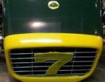

You do not have the required permissions to view the files attached to this post.


Top
 Profile  
Reply with quote  
PostPosted: January 2, 2020, 1:16 pm 
Offline
User avatar

Joined: October 24, 2008, 2:13 pm
Posts: 5326
Location: Carlsbad, California, USA
Thanks for posting, and for the details of the process too.

I took a look at the NZ site as well. That fellow did a lot of nice work.

Did you follow his example with the rear fenders too? I didn't see much about them in his build log. It looks like he did the front and rear fenders.

Cheers,

_________________
Damn! That front slip angle is way too large and the Ackerman is just a muddle.

Build Log: viewtopic.php?f=35&t=5886


Top
 Profile  
Reply with quote  
Display posts from previous:  Sort by  
Post new topic Reply to topic  [ 19 posts ]  Go to page 1, 2  Next

All times are UTC - 5 hours [ DST ]


Who is online

Users browsing this forum: Kinetic Research and 18 guests


You cannot post new topics in this forum
You cannot reply to topics in this forum
You cannot edit your posts in this forum
You cannot delete your posts in this forum
You cannot post attachments in this forum

Jump to:  
POWERED_BY