Critique my chassis design
Moderators: a.moore, horizenjob
-
Lemans1956
- Posts: 41
- Joined: May 13, 2016, 9:28 pm
- Building: Ferrari replica
Critique my chassis design
Hello fellow Locosters, I value the knowledge of the members here and would like to post my mid-engine chassis design. It is a work in progress so please be kind  . Please add any notes or comments for what I need to add or take away. The details are 1.5 in 16 gauge square tubing, round 1.75'' tube for the roll hoop and 1'' x 1'' secondary tubes. Cheers, -Vinny
You do not have the required permissions to view the files attached to this post.
-
carguy123

- Toyotaphobe
- Posts: 4829
- Joined: April 5, 2008, 2:25 am
- Building: Choppercrosser
- Location: Fort Worth, Texas
Re: Critique my chassis design
I would add some triangulation under the passenger compartment. This is a very big open area otherwise.
You'll probably be adding some cross members, etc. anyway to make mounting areas for seats and some other goodies.
You'll probably be adding some cross members, etc. anyway to make mounting areas for seats and some other goodies.
mobilito ergo sum
I drive therefore I am
I can explain it to you,
but I can't understand it for you.
I drive therefore I am
I can explain it to you,
but I can't understand it for you.
-
cs3tcr
- Posts: 1044
- Joined: December 29, 2007, 10:41 pm
- Location: Vancouver, BC
Re: Critique my chassis design
First off, I would look at adding a "terry hoop" for the dashboard. I would also look at adding a removable crossmember in your engine bay (it looks like there are nubs left over on your model from where a crossmember used to be). Also, depending on the body you're planning on running, you could add some structure outboard of your main chassis members in the cockpit area, like this:

Other than that, more triangulation in the front and rear bays of the chassis.
Other than that, more triangulation in the front and rear bays of the chassis.
-
Evlshnngns
- Posts: 42
- Joined: February 12, 2017, 7:57 pm
- Building: mid engine
Re: Critique my chassis design
I like all the room in the passenger compartment. I would like to now how it does with the FEA software.
-
seattletom
- Posts: 1511
- Joined: October 23, 2010, 2:40 am
Re: Critique my chassis design
Since you already have a balsa model, hold each end to simulate the suspension mounting points and apply some twisting force. That should show you areas of weakness. Add some more structure and see if that stiffens it up some.
Oh, and you might also want to think about adding a diagonal tube across your roll hoop.
You're on a slippery slope, many of us here started with a balsa model...
Oh, and you might also want to think about adding a diagonal tube across your roll hoop.
You're on a slippery slope, many of us here started with a balsa model...
Cheers, Tom
My Car9 build: viewtopic.php?f=35&t=14613
"It's the construction of the car-the sheer lunacy and joy of making diverse parts come together and work as one-that counts."
Ultima Spyder, Northstar 4.0, Porsche G50/52
My Car9 build: viewtopic.php?f=35&t=14613
"It's the construction of the car-the sheer lunacy and joy of making diverse parts come together and work as one-that counts."
Ultima Spyder, Northstar 4.0, Porsche G50/52
-
horizenjob

- The voice of reason
- Posts: 7652
- Joined: January 10, 2008, 4:47 pm
- Location: Massachusetts
Re: Critique my chassis design
Lemans56, I'll start by asking if you have seen the couple of builds on this site using Jack McCornack's Lalo bodywork? Just going by yur handle, perhaps you would like that style. It's something like a Lola Mk I.
I'll make some specific comments but want to stay that even with a good start there is a long way to go. The tubes in the frame need to work with each other, tubes in a place that make one chassis stiff don't do the same thing in another chassis. Then they also need to be good at putting nodes in places that you want to feed loads into the chassis. Mostly suspension, coilover and motor mounts.
In this type of chassis the transitions from the large passenger area to the smaller front suspension box area behind the passengers is difficult. I think you see that because the flow isn't quite right there.
My first specific comment is that the tubes directly behind the passengers back be removed. They pose a threat to the passengers and also do not serve a purpose ( well, you may have a plan for them but we can't tell yet ). Since those tubes join the cross wise tube behind the passenger's shoulders, but not at a node - they are dead weight. When you remove them, the frame doesn't look quite right because you are trying to use them to support the rear of the upper rail. I hope the description makes sense it's hard without labels on the tubes. So what I am saying is that problem is there anyway.
Look carefully at the frame cs3tcr has posted. It does not extend so far to the rear as your frame, because there is no need to support anything so far back. The transaxle will support itself and the rear suspension mounts do not need to extend behind the halfshafts. Notice that suspension only has a single upper radius arm link and uses trailing arms. It uses a reverse wishbone for the lower link so that connects right below the upper link.
Another thing you can see that that frame uses is a box ( prism shape here ) on the outside of the passenger compartment to make that part of the car stiff. It's basically a shelf where the drivers elbow would go and it should provide a lot of strength and some protection too. This is a common design element , for instance the GT40, Gullwing and many others.
Tom is right you can learn a lot from handling the frame and trying to bend it. You can also do that in software and we can make some recommendations for free programs to do this. It's a good amount of work to learn these, but it will also be a good amount of work to make some more models.
You could use some models of a human and an engine and transaxle soon too. They don't have to be fancy, but you really need to know where mounting bolts and how long your arms and legs are etc. soon.
Keep at it!
Marcus Barrow - Car9 an open design community supported sports car for home builders!
SketchUp collection for LocostUSA: "Dream it, Build it, Drive it!"
Car9 Roadster information - models, drawings, resources etc.
SketchUp collection for LocostUSA: "Dream it, Build it, Drive it!"
Car9 Roadster information - models, drawings, resources etc.
-
Lemans1956
- Posts: 41
- Joined: May 13, 2016, 9:28 pm
- Building: Ferrari replica
Re: Critique my chassis design
Thanks to everyone who took the time to reply. It has given me lots to consider. Assembling the basla#1 was very enjoyable as I could feel the model gain stiffness as sections were added. I'll move to version 2.0 and report back with the results. Cheers, Vinny
E
E
-
Lemans1956
- Posts: 41
- Joined: May 13, 2016, 9:28 pm
- Building: Ferrari replica
Re: Critique my chassis design
I reworked the model yesterday and will post the updated images this evening. I thought it would be helpful to show the Corvette rear suspension and Porsche Transaxle I'm running to illustrate why the rear cross member looks the way it does. Thank you to all who replied here, it's a great help. Stay tuned. Vinny
You do not have the required permissions to view the files attached to this post.
-
carguy123
- Toyotaphobe
- Posts: 4829
- Joined: April 5, 2008, 2:25 am
- Building: Choppercrosser
- Location: Fort Worth, Texas
Re: Critique my chassis design
Do the axles fit the Porsche diff and Corvette uprights without any special axles or anything?
mobilito ergo sum
I drive therefore I am
I can explain it to you,
but I can't understand it for you.
I drive therefore I am
I can explain it to you,
but I can't understand it for you.
-
horizenjob
- The voice of reason
- Posts: 7652
- Joined: January 10, 2008, 4:47 pm
- Location: Massachusetts
Re: Critique my chassis design
Thanks for the pictures, that's a help.
Have you considered running the transaxle upside down? That means you don't have to flip the ring and pinion maybe? It puts your engine several inches lower, so this depends on ground clearance, oil pan etc. too.
Do those Corvette arms mount directly fore and aft on the inboard end?
You may want to get some 2x2 at Home Depot and also do some concurrent full size modeling off your transaxle cradle there.
In your model above it looks like you have a couple of tubes to indicate a front roll hoop or dashboard? I think they need to move back a bit. and then that provides a place for a "W" truss above the driver's legs that provides nodes for the front suspension box to attach at.
Don't be afraid to make your own rear suspension arms, I think other things will work out easier for you if you do that, but keep at what your doing now until you have a good feeling for all these tradeoffs.
Marcus Barrow - Car9 an open design community supported sports car for home builders!
SketchUp collection for LocostUSA: "Dream it, Build it, Drive it!"
Car9 Roadster information - models, drawings, resources etc.
SketchUp collection for LocostUSA: "Dream it, Build it, Drive it!"
Car9 Roadster information - models, drawings, resources etc.
-
Lemans1956
- Posts: 41
- Joined: May 13, 2016, 9:28 pm
- Building: Ferrari replica
Re: Critique my chassis design
carguy123 wrote:Do the axles fit the Porsche diff and Corvette uprights without any special axles or anything?
Porsche 930 CV's fit the 28 spline Corvette shafts and will bolt up to the tranny flanges. Thanks, Vinny
-
Lemans1956
- Posts: 41
- Joined: May 13, 2016, 9:28 pm
- Building: Ferrari replica
Re: Critique my chassis design
. Thanks, I will keep that in mind.horizenjob wrote:Thanks for the pictures, that's a help.
Have you considered running the transaxle upside down? That means you don't have to flip the ring and pinion maybe? It puts your engine several inches lower, so this depends on ground clearance, oil pan etc. too. I'll be running an Audi engine bolting up to the trans like OEM, no adapter or flipping and the height will be what it is..
Do those Corvette arms mount directly fore and aft on the inboard end? I attached my drawing which shows where they mount in relation to the axle.
You may want to get some 2x2 at Home Depot and also do some concurrent full size modeling off your transaxle cradle there. Already on it !
In your model above it looks like you have a couple of tubes to indicate a front roll hoop or dashboard? I think they need to move back a bit. and then that provides a place for a "W" truss above the driver's legs that provides nodes for the front suspension box to attach at. I picture a horizontal 'W' across the cowl or scuttle, correct ?
Don't be afraid to make your own rear suspension arms, I think other things will work out easier for you if you do that, but keep at what your doing now until you have a good feeling for all these tradeoffs.
You do not have the required permissions to view the files attached to this post.
-
Lemans1956
- Posts: 41
- Joined: May 13, 2016, 9:28 pm
- Building: Ferrari replica
Re: Critique my chassis design
Yesterdays work, Tilted 'Balsa and Chips', 
.I removed the intrusive tubes behind the passenger comp. - re-did the roll hoop with new back leg supports, added diagonals coming up off the rear hip to the upper roll bar connector. added x-bracing to the floor and front susp member.. added a center tunnel in the pass comp tying the rear firewall and front cowl together. and a front radiator extension.
.
You do not have the required permissions to view the files attached to this post.
-
Lemans1956
- Posts: 41
- Joined: May 13, 2016, 9:28 pm
- Building: Ferrari replica
Re: Critique my chassis design
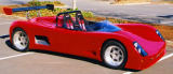
Here's an image of the style of body that will sit on the chassis.
.
.
You do not have the required permissions to view the files attached to this post.
-
carguy123
- Toyotaphobe
- Posts: 4829
- Joined: April 5, 2008, 2:25 am
- Building: Choppercrosser
- Location: Fort Worth, Texas
Re: Critique my chassis design
Lemans1956 wrote:carguy123 wrote:Do the axles fit the Porsche diff and Corvette uprights without any special axles or anything?
Porsche 930 CV's fit the 28 spline Corvette shafts and will bolt up to the tranny flanges. Thanks, Vinny
How lucky can you get!!! That's awesome.
Where are you going to get the body?
mobilito ergo sum
I drive therefore I am
I can explain it to you,
but I can't understand it for you.
I drive therefore I am
I can explain it to you,
but I can't understand it for you.
Who is online
Users browsing this forum: No registered users and 5 guests