LocostUSA.com

Learning how to build Lotus Seven replicas...together!
It is currently May 15, 2024, 12:16 pm

All times are UTC - 5 hours [ DST ]


Post new topic Reply to topic  [ 7 posts ] 
Author Message
PostPosted: January 21, 2009, 11:15 am 
Offline
User avatar

Joined: July 22, 2007, 10:58 pm
Posts: 388
Location: Zagreb, Croatia
After finding out that my hole saw tube mieter will not do (due to the complexity of the cuts) and having no laser cutting service for tubing available locally, I decided to try and use the solidworks to trim the tubing virtually and make cutting templates, but with a special twist because I am to lazy to cut paper templates.. :)

The basic concept is to use the weldment feature to put the tubes in place, and then trim them using the trim feature, and then unwrap the tubing as if it was made of a wrappe sheet in the first place..

Firstly, I did find a HOW TO manual for this on the FSAE site. But, that one included a very complicated way of "cutting" the tubes to get a flat sheet.. so here is a simpler solution that works in the same way, but instead of cutting the tubes to get a sheet, we will use different weldment profiles that have the cut allready in them.


1. Make a new weldment profile.

Depending on what tubing you want to use, you should allready have a library of tubing for your project. Solidworks doesn't have much, but you can easily make new profiles that you need by making new weldment profiles and saving them in solidworks data/weldment profiles/tubing/.... directory.

Here is a basic 40x1.5 mm profile
Image

You need to edit the sketch. Firstly, instead of 40 m OD, make 40mm ID and a really thin wall... lets say 0.1 mm

Then make a thin slit in the sketch. and save it under a different name. but in the same directory as the original template
Image


Top
 Profile  
Reply with quote  
 Post subject:
PostPosted: January 21, 2009, 11:31 am 
Offline
User avatar

Joined: July 22, 2007, 10:58 pm
Posts: 388
Location: Zagreb, Croatia
Before you start cutting tubes and making templates.. First check your project, and check the sketches to see if you accidentally moved any points around... it can happen..


1. Trim the tubes using the trim feature in Solidworks. This "virtually" cuts the ends of the tubes as you would need them in reality. This is a very important step as you have to pay special attention which tube comes first and how you will assemble, especially if you have more than 3 tubes in a joint. Even if you have 5 tubes in a joint, some tubes will be trimmed by only one tube.. so take you time and carefully trim the tubes and think how you will assemble it in reality.

2. After you trimmed the tubes, you need to change the tube profile for the new thin profile with a slit
Image

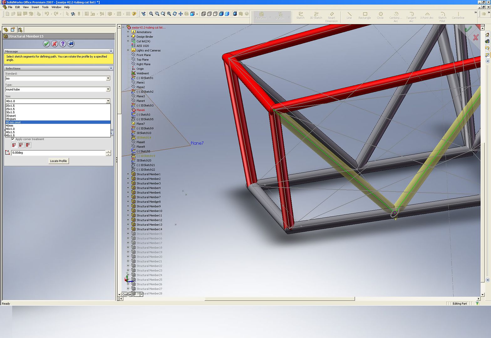
It is important to only change the profile for ONE tube at a time, the tube you will be copying out of the project. as solidworks will update the cuts automatically, if you change all the profiles at once, your trims will change dramatically and will not work..

4. after you changed the profile, find it in the list on the left (select the TRIM feature not the structural member, rightclick and select "insert into New part"
Image

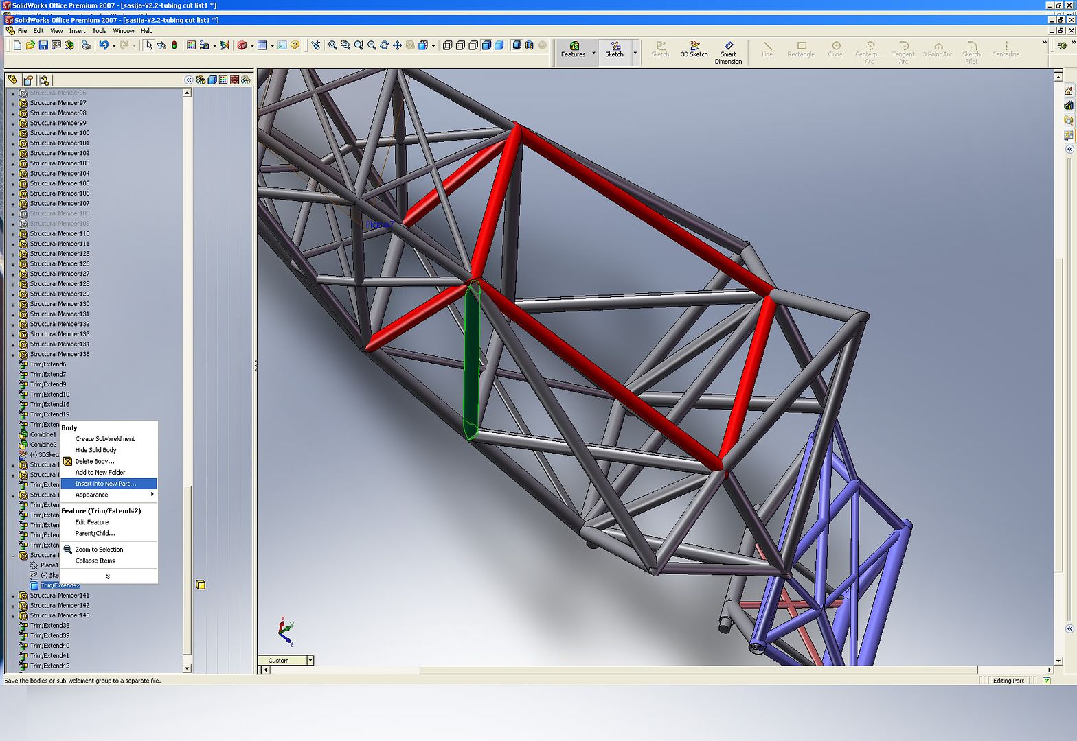
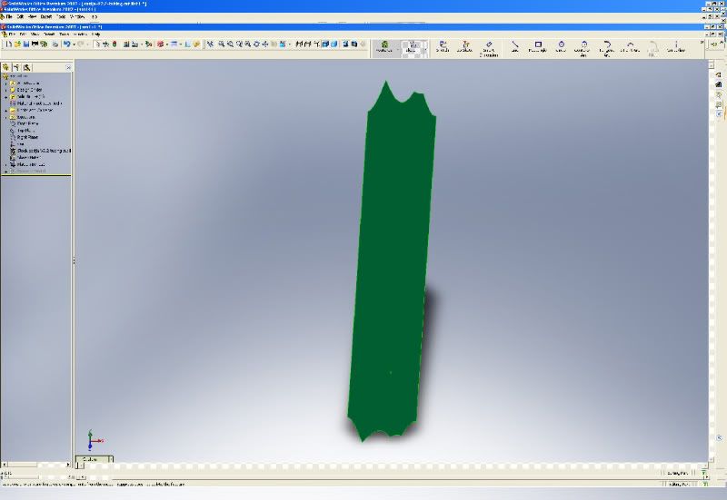
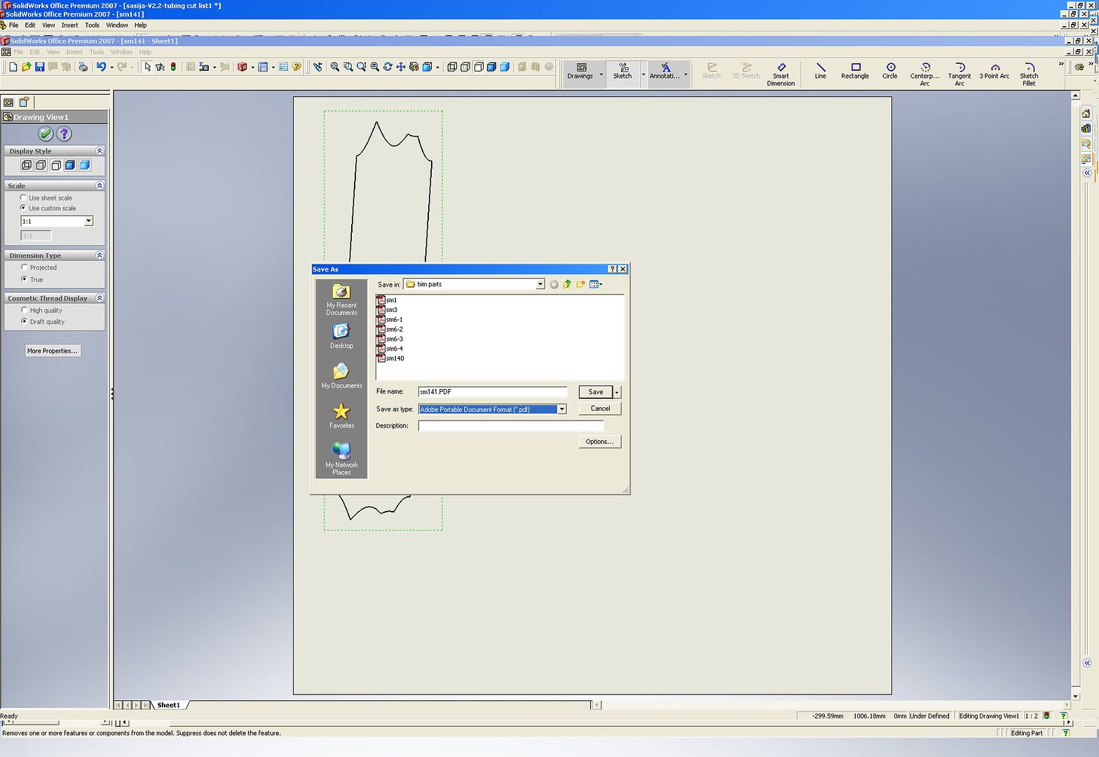
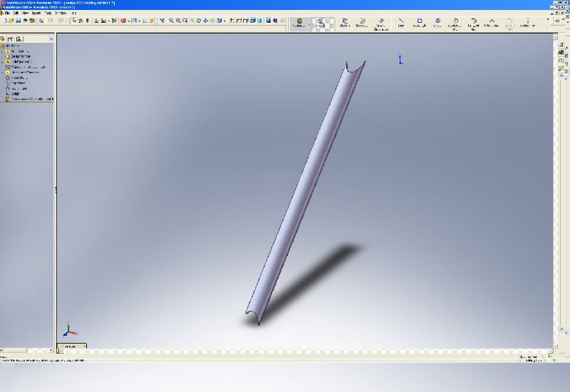
5. this will give you a separate part, all trimmed and ready :)
Image

6. Turn it and find the slit on the inside of the tube, select it and go Insert - Sheet metal - Bends
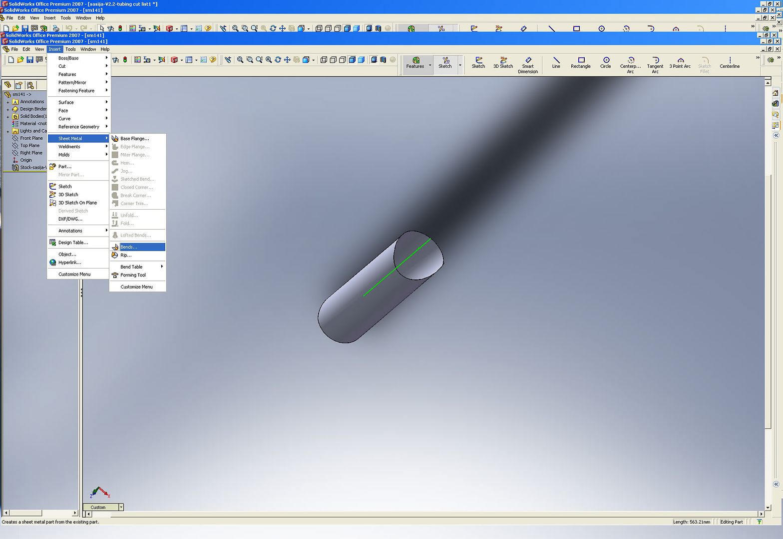
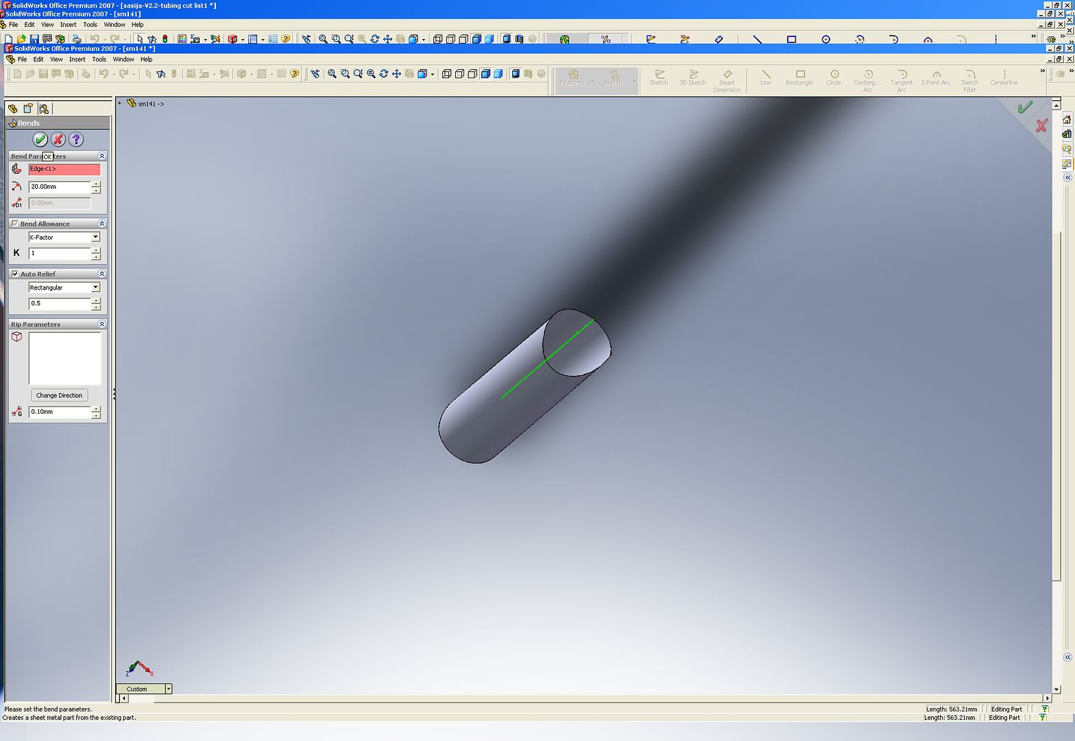
Image

7. click OK
Image

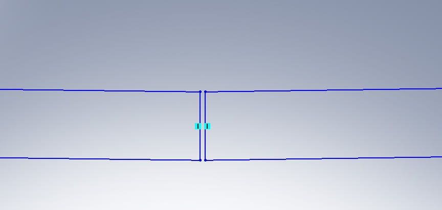
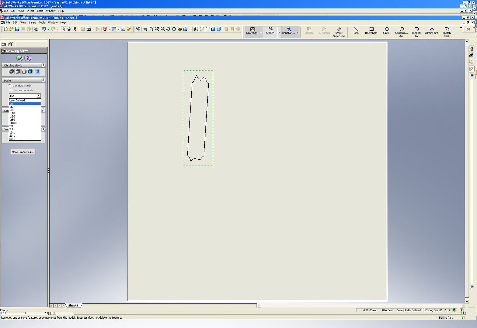
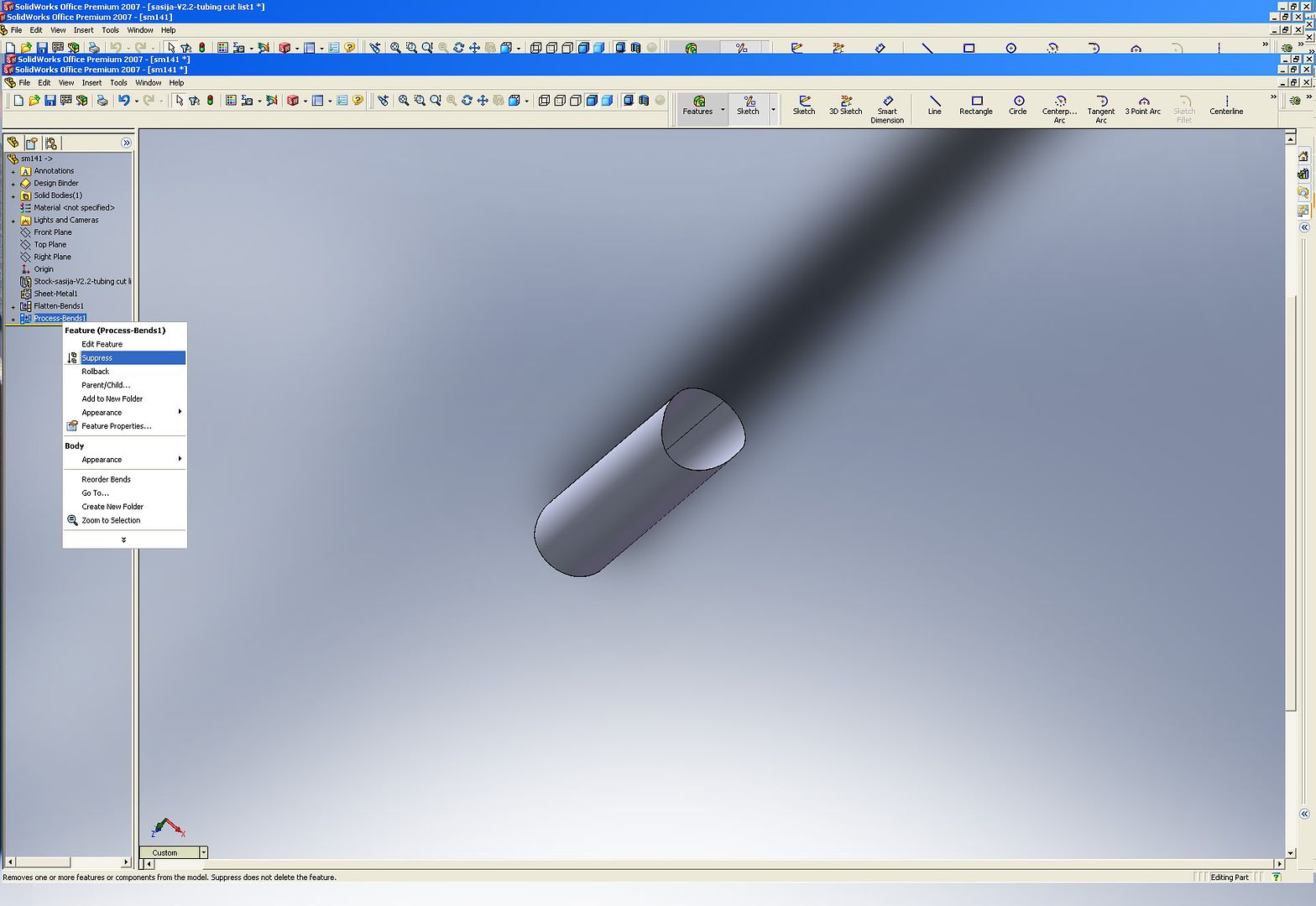
8. in the left list right click Process-bends and select Surpress.. this flattens the folded sheet, which is your tube
Image

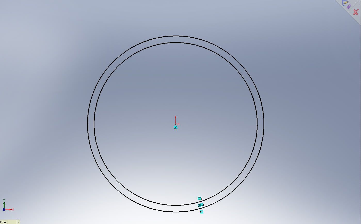
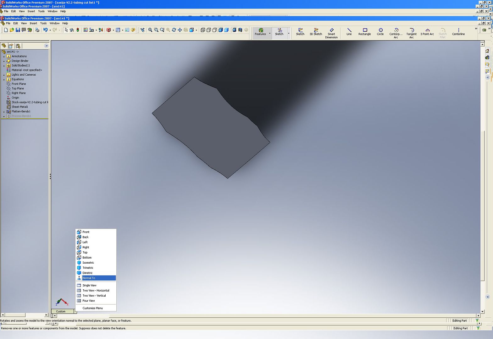
9. Select View- Normal To...
Image

10. and click onto the face of the sheet...
Image

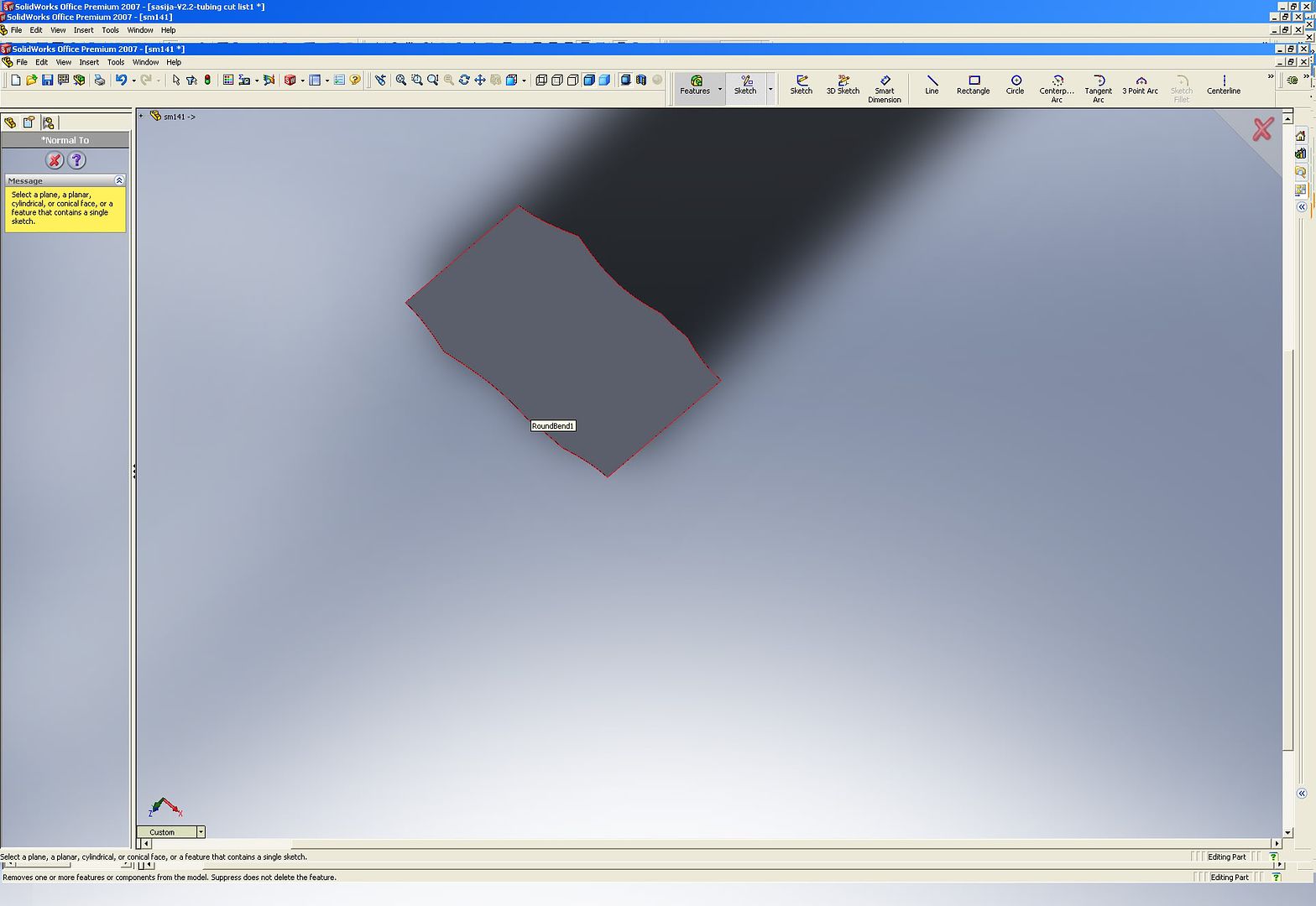
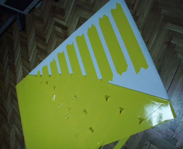
this will give you a nice projection of the whole sheet

Image


Top
 Profile  
Reply with quote  
 Post subject:
PostPosted: January 21, 2009, 11:35 am 
Offline
User avatar

Joined: July 22, 2007, 10:58 pm
Posts: 388
Location: Zagreb, Croatia
11. select Make drawing from part / assembly and choose a nice large custom sheet size... custom because then it has no additional tables etc..
Image

12. drag your CURRENT VIEW (important) onto the sheet..
Image
select 1:1 scale

At this point you could just print it onto paper but normal printers are not big enough. In which case you could print just the ends and tape them onto the tubes.. but then you have to worry about orientation and distance between the two.. so I propose you do the following..


Top
 Profile  
Reply with quote  
 Post subject:
PostPosted: January 21, 2009, 11:42 am 
Offline
User avatar

Joined: July 22, 2007, 10:58 pm
Posts: 388
Location: Zagreb, Croatia
13. SAve the drawing as PDF
Image

14. Import the PDF-s into a graphic program , such as freehand, or corel draw / illustrator, autocad.. etc..

there you can add some info on the tube. I added its' structural member number and tube dimension and wall thickness..

Image

15. Then I took those files to a graphic studio that cuts self adhesive foil. :)
this is a cheap and widespread service over here...

We cut the sencils in 1:1
Image

Image

and in the end, after sticking on some transfer foil (to transfer the sencil from the backing onto the tube) we get:

Image


clean the tubing very well.. with acetone... and using a ruler of sort to have the tube paralel to the sencil, apply the stencil onto the tube

Image

Image

Image

Image

Image


Then it is just a matter of using thin cutting wheel for rough trims + thick one for fine work and hand file for final adjustment.

Have in mind that the stencil has to do with the surface of the tube, you will have to use your imagination to cut the tube in a way to account for the wall thickness... but after you d o2 of them it gets fast...

Image

Image

Image


Real benefit of this method will be shown when doing really strange joints.. :)


Top
 Profile  
Reply with quote  
 Post subject:
PostPosted: January 21, 2009, 12:41 pm 
Offline
Mid-Engined Maniac

Joined: April 23, 2006, 8:26 pm
Posts: 6422
Location: SoCal
How do you take into account tubing wall thickness? The issue is that is some junctions you have to trim the ID while on other's the OD is the problem. The more acute the angle is the bigger the problem becomes. A good example would be two tubes coming together with only, say, 20 degrees between them, so the tube cuts will be long and pointy. On the outside, the OD of the tube will be one value while the ID will be very different.

For selling kits this would be great, but for a one-off, I don't know if it's worth the time. Then again I actually enjoys fitting up tubes.

_________________
Midlana book: Build this mid-engine Locost!, http://midlana.com/stuff/book/
Kimini book: Designing mid-engine cars using FWD drivetrains
Both available from https://www.lulu.com/


Top
 Profile  
Reply with quote  
 Post subject:
PostPosted: January 21, 2009, 3:21 pm 
Offline
User avatar

Joined: July 22, 2007, 10:58 pm
Posts: 388
Location: Zagreb, Croatia
KB58 wrote:
How do you take into account tubing wall thickness? The issue is that is some junctions you have to trim the ID while on other's the OD is the problem. The more acute the angle is the bigger the problem becomes. A good example would be two tubes coming together with only, say, 20 degrees between them, so the tube cuts will be long and pointy. On the outside, the OD of the tube will be one value while the ID will be very different.

For selling kits this would be great, but for a one-off, I don't know if it's worth the time. Then again I actually enjoys fitting up tubes.


this method gives you the "exact" tube surface cut you have to do.. and I agree it doesn't adress the ID problem. After doing a couple of tubes I found that I can adress the ID problem pretty well by myself, just by grinding it differently... in the end doing a bit by hand too... but always respecting the cut line defined by the sticker..

it is not no where near easy as having them laser cut.. but this method has a couple of strong points

1. it references both ends of the tube with respect to each other
2. handles strange joints, like the one I have where I have a tube coming right into another 90 deg joint, can't make that one with a holw saw..

I do not know how it is in the US, but over here cnc cut adhesive foil is cheap enough for me to do the whole frame like this... If I wanted to spend even less, I'd jut cut the ends in foil and then spend more time sticking them onto tubing in the right position...
I spent about 3 hours preparing the files for the main part of the frame, and that includes doing screenshots for the forum, so I think it is much faster than any other method in fact..

you are right on two points... first this would be a good addon to a set of kit car plans for sale, and I too find fitting up tubes strangely relaxing especially after I bought some ear protectors :D


Top
 Profile  
Reply with quote  
 Post subject:
PostPosted: January 21, 2009, 3:22 pm 
Offline
User avatar

Joined: July 22, 2007, 10:58 pm
Posts: 388
Location: Zagreb, Croatia
I will post some more pics of difficult joints next week, I have a meeting with a GT-R tommorow.. :twisted:


Top
 Profile  
Reply with quote  
Display posts from previous:  Sort by  
Post new topic Reply to topic  [ 7 posts ] 

All times are UTC - 5 hours [ DST ]


Who is online

Users browsing this forum: No registered users and 3 guests


You cannot post new topics in this forum
You cannot reply to topics in this forum
You cannot edit your posts in this forum
You cannot delete your posts in this forum
You cannot post attachments in this forum

Jump to:  
POWERED_BY