LocostUSA.com

Learning how to build Lotus Seven replicas...together!
It is currently April 18, 2024, 11:25 pm

All times are UTC - 5 hours [ DST ]


Post new topic Reply to topic  [ 166 posts ]  Go to page Previous  1 ... 8, 9, 10, 11, 12  Next
Author Message
 Post subject: Re: The GWTFFM
PostPosted: October 1, 2019, 9:14 pm 
Offline
User avatar

Joined: March 30, 2011, 7:18 am
Posts: 1615
Location: central Arkansas
300D50 wrote:
I've got a 2008 Audi Q7 190A alternator on the way ... it's liquid cooled


That used to be the domain of seriously expensive industrial equipment.

There's a chart from AC Delco floating about the web that shows the output of automotive, marine, OTR, and industrial alternators. Something it mentions is that the rated output of alternators is *cold*. As the alternator warms up the amperage falls off sharply. And more sharply for the small-format modern alternators than for the old ones. Some of the 100 amp alternators would drop to 50A or less after a few minutes at full load.


Top
 Profile  
Reply with quote  
 Post subject: Re: The GWTFFM
PostPosted: November 14, 2019, 1:04 pm 
Offline
User avatar

Joined: August 11, 2013, 6:03 am
Posts: 573
Location: CNY
Nothing much new, winter and the time change/darker evenings hit like a dang mule and derailed my efforts a bit.

I'm going with a gilmer drive for the alternator and sump pump, I ordered in a cheap kit a few days after the alternator came in.
The ratios work out close to what I need, and the sump pump needs a gilmer anyways.

The original OAD (over-run clutch) on the alternator is getting turned down (Well, a new one is, but semantics) and press-fit into the bored out pulley from the kit.

One little "issue" is the Q7 alternator does not have computerized field control, so the ECU can't disengage it like the factory one.

I'm going to look into doing some surgery to the Q7 alt to breakout the field wiring and run a Mazda regulator.
Or just live with it the way it is.
The joy of custom stuff.

Still have yet to decide where I want to mount the alternator, but I'm leaning towards the existing top mount more and more.

A recent addition to my toolset is a bare bones china 3D printer, for those times when I want to turn 5+ hours into a plastic test part.


Top
 Profile  
Reply with quote  
 Post subject: Re: The GWTFFM
PostPosted: January 7, 2020, 4:24 am 
Offline
User avatar

Joined: August 11, 2013, 6:03 am
Posts: 573
Location: CNY
Progress was made.

I had switched from the 1990 front cover to the 2004 RXone for a multitude of reasons a while back
One among them to get rid of the CAS and go to trigger wheel , engine control, and all that lovely jazz from a 06 RX-8.

One of the sticking points is the RX-8 front hub was slightly shorter than the S5 one, so the e-shaft stuck out about 3mm.

That means the front bolt won't tighten, torrington bearings wouldn't get pre-loaded, bad times would be had by all.
I could have stuffed a spacer on and called it a day, but in the end I couldn't really see how I could do that and still seal the e-shaft safely.

The other option was to machine the S5 front hub to take the trigger wheel on the back side, to keep it in alignment with the sensor.

I didn't end up getting photos of the hub being machined, mainly because it's cast iron and made an absolute mess.

The back side had to OD brought down to match the front, up to the back face of the pulley flange.

The flange got shaved down from 12mm to 8mm thick off the front face, so the gilmer pulley could slip back a bit further. I couldn't machine further material off the flange without hitting the balance dimples.

I did start snapping photos as I bored the gilmer drive pulley back 0.05" to get a little bit more recess.
Image

Test-fit, seeing if I had a good seat.
Image

Trigger wheel bolted to the flange from the back side, using OE RX-8 pulley bolts.
Slipped into the pulley to verify that everything lines up.
Image

Image

There's roughly 3mm gap between the trigger wheel and the edge of the pulley.
Image

Side-by-side, modified S5 front hub on the left, stock RX-8 on the right.
The trigger wheel is slightly lower, but that shouldn't cause any issues. I couldn't machine the flange to keep it flush without hitting the dimples andrisking the balance being off.
Image

Image

The reduction in protrusion wasn't as much as I was hoping, being only 9mm shorter, but I now don't have to worry about belt slip, and can drive the dry sump pump.
Image

The threaded holes need to be chased, and then I can get longer flange bolts so I can hold the pulley on with nuts.


Top
 Profile  
Reply with quote  
 Post subject: Re: The GWTFFM
PostPosted: January 7, 2020, 4:25 am 
Offline
User avatar

Joined: August 11, 2013, 6:03 am
Posts: 573
Location: CNY
Also completed the alternator pulley on Monday, but work on it actually started back in October 2019, so some photos and steps were done out-of-order.
I've arranged them to best tell the narrative as if I was doing everything all in one shot.

2007/2008 Audi Q7 190A liquid cooled alternator with the OAD pulley removed.

Image

Back of same alternator.
Image

OAD chucked in the lathe, getting the serpentine ribs removed.
Image

Machined down to 48mm (1.890").
Not shown is flipping and bringing down the other side.
Image

Trimmed the back of the gilmer pulley to release the guide flange.
Image

The pulley was bored out to 1.888" (~47.95mm)
Image

Image

Gilmer pulley went into the toaster oven on max broil convection for an hour, which is roughly 500°F
OAD went into a 3°F freezer for the same time.
I had two smaller sections of aluminum plate that I sat on top of the gilmer pulley in the oven, to get a little more thermal mass.
Likewise with the larger plate below, that was out in 30° weather before it came in.

Slid in like a dream, just had to lean on it slightly to get it cozy.
Image

Image

Image

I went flush because I can vary the spacing by machining down the spacer ring that slips over the alternator shaft.
That needs to be done anyways to account for belt alignment, so might as well allow for the maximum adjustment.

Now to get the front cover trimmed down to fit the alternator.


Top
 Profile  
Reply with quote  
 Post subject: Re: The GWTFFM
PostPosted: January 8, 2020, 12:55 am 
Offline
User avatar

Joined: August 11, 2013, 6:03 am
Posts: 573
Location: CNY
Image

Image

Image

Image

Image

Image

Image

Image

Image


Top
 Profile  
Reply with quote  
 Post subject: Re: The GWTFFM
PostPosted: January 9, 2020, 1:39 am 
Offline
User avatar

Joined: August 11, 2013, 6:03 am
Posts: 573
Location: CNY
Time to make the centering bushing.
Image

11.5mm OD, 8.03mm ID
Image

Parted off and ready to machine the front face.
Image

Forgot to take a final shot before pressing it in.
Had to give the hole in the casting a quick zip with a 29/64 drill to clear up some draft angle before things could proceed.

Pressed in.
I used one of the alternator bolts and a nut to draw it in, and like a dope forgot to put a sacrificial washer in place.
Oh well nobody will see it in use.
Image

One might wonder why I removed material from the mount just to put it back with the bushing.
Simple reason is, I didn't know exactly how much needed to be removed till I had everything mounted up and shimmed.
Image

I left the bushing a few mm short so that I can potentially press it out down the road.
Image


Top
 Profile  
Reply with quote  
 Post subject: Re: The GWTFFM
PostPosted: January 10, 2020, 2:11 am 
Offline
User avatar

Joined: August 11, 2013, 6:03 am
Posts: 573
Location: CNY
Dry Sump Pump Pulley Time!

One of the pumps I bought came with a 28 tooth L profile pulley, 1" wide.
The gilmer kit I bought uses an L profile belt that's 1.5" wide. E-shaft pulley is 34 tooth, and a water pump pulley in 28 tooth.

Ideally, you're not supposed to to run a dry sump pump over ~5000RPM due to the chance of cavitation, but since I'm not running a pressure stage I think I can get away with running it faster.

I decided to turn the worn and beaten up dirt car pump pulley into a hub I could bolt the waterpump pulley to.
Reason is, it already has setscrew holes drilled and tapped, is bored to fit the pump shaft, and has the keyway broached.

I used the pump shaft as a mandrel when machining, because it was simple and ensured concentricity.
Image

Trimmed off the pulley, leaving the web and hub.
Image

Image

I turned the hub boss down to 1.000" (The pump is SAE, and 1" worked.) and skimmed the web into a flange surface.
I believe the flange OD came out to 3" but it wasn't critical so I didn't put much thought into it
Image

The back side of the flange was skimmed to clean it up a bit, in case I decided to mount anything to the opposite side. I left the sweeping radius intact to reduce stress risers.
Image

I didn't take any photos of boring the centering ring on the waterpump pulley out to a slip fit on the hub.
Image

No threaded holes yet, they're going to be zipped in on the FADAL tomorrow.
Image

Image

In case you're wondering, the grime that's getting all over is primarily powdered graphite from a different job that was ran on the lathe, plus ultrafine cast iron dust, and WD-40.


Top
 Profile  
Reply with quote  
 Post subject: Re: The GWTFFM
PostPosted: January 10, 2020, 11:58 pm 
Offline
User avatar

Joined: August 11, 2013, 6:03 am
Posts: 573
Location: CNY
Hub fixtured in.
Image

44mm bolt circle punched. Holes are 5mm.
Image

Image

Threaded M6x1.
Image

Image

Image

Mocking up. Good thing I waited to do the sump plate, I would have had some interference problems where the pump was slated to mount.
Image

Image


Top
 Profile  
Reply with quote  
 Post subject: Re: The GWTFFM
PostPosted: January 12, 2020, 1:10 am 
Offline
User avatar

Joined: August 11, 2013, 6:03 am
Posts: 573
Location: CNY
Small reward to myself for making progress.
Image

Pulleys line up nicely.
Image

The 30" belt that came with the kit is too short for this setup.
Image

Getting there.
Image

I ended up cutting the 30" belt and using it to measure out for a new one.
The minimum length appears to be 44.5" with the pump tight to the keg.
The closest "standard" belt size was a 45" sold by Jegs.
Ordered one up, should be in by Friday.

Now I need to put some more time into CAD on the dry sump plate, aided by the foam board.


Top
 Profile  
Reply with quote  
 Post subject: Re: The GWTFFM
PostPosted: January 13, 2020, 12:28 pm 
Offline
User avatar

Joined: October 24, 2008, 2:13 pm
Posts: 5326
Location: Carlsbad, California, USA
Nice work - very impressive stuff.

Cheers,

_________________
Damn! That front slip angle is way too large and the Ackerman is just a muddle.

Build Log: viewtopic.php?f=35&t=5886


Top
 Profile  
Reply with quote  
 Post subject: Re: The GWTFFM
PostPosted: August 6, 2020, 11:56 am 
Offline
User avatar

Joined: August 11, 2013, 6:03 am
Posts: 573
Location: CNY
Well, still at the same place I was in January, alternator mount needs to be fabricated and I need to finalize the pump mounting and etc.

I had left off with the pump torn down, in process of making a new end plate to remove the oil pressure regulator section.

Now, I'm thinking of just making plugs and pressing them into the existing part to block the passages. Not elegant, but it will get me closer to my end goal with less design work. I can revisit making a new piece later on down the road as time permits.

I've also decided, just now, that my "trash screens" before the pump stages will go inside the sump plate at the pickup slots.
Saves me having to deal with any inline sandwich issues, and gets me one more step closer. If I have trash in the sump, I have bigger issues than the pump getting wadded up.

Also on the agenda, I'm going to admit defeat, and wire the alternator with a flying pigtail between the brush holder/regulator module. I have been sitting on my thumbs too long trying to keep it all self-contained and pretty, when I really just need it to work.
It will never be an off-the-shelf part, so trying to keep the same connectors is pointless.


Top
 Profile  
Reply with quote  
 Post subject: Re: The GWTFFM
PostPosted: August 18, 2020, 11:27 am 
Offline
User avatar

Joined: August 11, 2013, 6:03 am
Posts: 573
Location: CNY
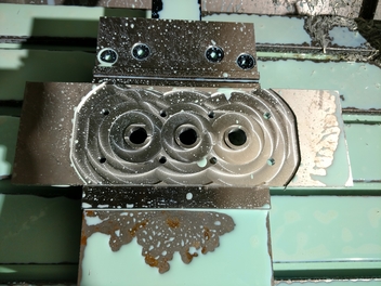
Pump went back in the mill for some more work.

Image

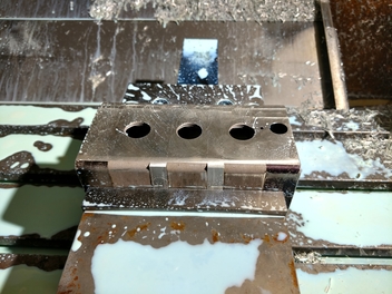
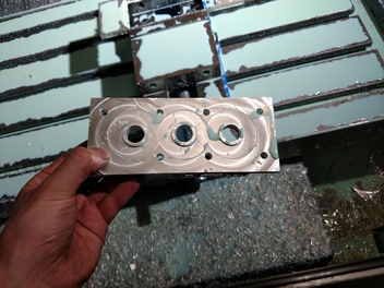
I pressed out the steel sleeve for the pressure regulator before hand, I had neglected to do it when I decked it last time.
It will eventually get replaced with a solid aluminum plug, press-fit with loctite 680.
Image

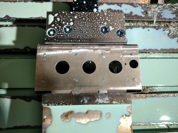
Four holes milled, two in each endplate, 5mmIDx6mm deep. M6 fasteners being used.
Spacing and depth was chosen to clear the internal passageways and the tension bolts, so I don't have leaks.
Image

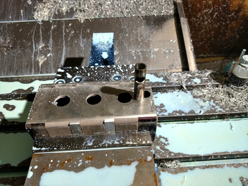
Four more holes, 5mmIDx12mm deep, in the two spacer plates.
There's not enough wall thickness to easily place holes in the pumping chambers, they would either be ~3 thread engagement, or foul with the tension bolts that hold the pump together.
Image

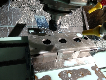
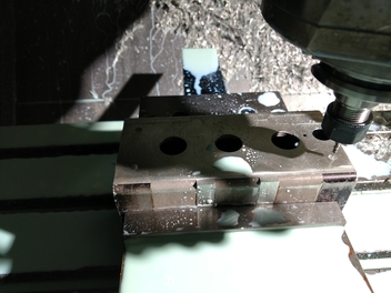
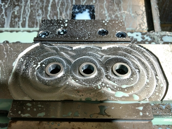
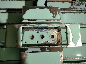
Final touch was boring the inlet holes out to 22mm to clean off most of the thread remnants.
22mm isn't quite 7/8, so there's a little bit of the thread major diameter still showing.
I didn't feel like going too much larger though, as I already weakened this area by milling off the fitting bosses.
Any gaps the thread remnants form on the flange bosses will be dealt with by using 518 sealant.
Image

Speaking of the flange, here's the start of it.
First order of business, true up an offcut of 0.375" plate aluminum.
Image

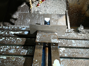
Sitting flat, fixtured, and ready to mill.
Image

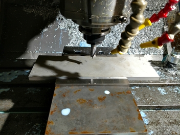
The bosses are 21.95mm OD, 2mm high, to give a tight but still "slip" fit to the pump, allowing positive location and hopefully negating the need for o-rings or seals.
The center through holes have a 16mm ID, chosen to be slightly larger than the -10AN fittings that are normally used with the pump.
Image

Eight tight clearance holes for M6 fasteners done.
Image

Outer profile machined.
If you look closely, I seem to have an unequal centering along the Y axis, which pushed this operation dangerously close to nipping the parallel bars on cutoff...
Near as I can tell, I must have fat fingered the stock size in CAM, since the work offsets were set with the probe to within a few thousandths.
Image

I may actually have to remake this down the line, since the part seems to have pulled up slightly while running the finish passes on the bosses.
This wasn't noticed till after the whole program was completed, but it appears to be ~0.010" or so.
It still fits the pump, but the sealing might not be optimal.
Image

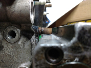
Setting the pump with flange next to the engine (already on a sheet of aluminum plate), we just barely clear the lower PS/AC bracket stud on the front iron.
I won't be using that stud for a bracket in the final build, but it's a happy occurrence that it clears, since then I don't have to extract it till later on, and can continue using it for mounting the engine to the stand in the interim.
Image

I used the flange as a tap guide, and threaded the 8 mounting holes. Didn't get a photo though.
I still need to get a bottoming tap or modify a plug tap, but for now I can at least bolt it down.

Next order of business is to tackle either the upper alternator bracket or the idler/tensioner for the belt.

The sump plate is going to wait, since that needs more consideration for the engine mounts, axle brace pickup, and other tie-in points.

The alternator brush holder will be getting yet more invasive modification to install a flying lead to the outside world, and that started as well.
I misplaced my hand drawn regulator schematic, so I'll have to find it again before I can go further on that.


Top
 Profile  
Reply with quote  
 Post subject: Re: The GWTFFM
PostPosted: August 25, 2020, 11:32 am 
Offline
User avatar

Joined: August 11, 2013, 6:03 am
Posts: 573
Location: CNY
Blanking pin machined out of aluminum, next to the steel sleeve that was pressed out.
No pics of the machining, had some graphite dust on the lathe and that doesn't mix with optics to nicely.
Image

I'm using the existing screw-in plug on the one end so I don't have to machine any threads.
Image

Nice smear of Loctite 680 retaining compound.
This is a mild press fit, turned to the same OD as the steel piece was.
Image

Tapped partially in place, enough to start the plug in and use it to press the rest of the way.
Image

Tightening the plug, pressing in the blanking pin.
Image

Nearly there.
Image

I made the pin oversized on length, so that I could tweak where the the plug stopped when it was tightened down.
Image

Flush, or maybe .001 under the surface.
Image

I decked the plug down till the flat of the hex aligned with the body of the pump, since having a point of the hex overhanging would irk me to no end.
Image

I still need to get/make a bottoming tap and finish the threads, but that's all the major machine work on the pump finished.
Image

I need to get new o-rings, give it a full cleaning, then slap the gears back in and it's done.


Top
 Profile  
Reply with quote  
 Post subject: Re: The GWTFFM
PostPosted: September 4, 2020, 10:09 am 
Offline
User avatar

Joined: August 11, 2013, 6:03 am
Posts: 573
Location: CNY
~$10 in plastic and ~21 hours of print time later, we have the corners of the upper/lower sump plate that the pump mounts to.
This was on rather "fat" settings of 0.4mm layers for a quick print, so detail is slightly compromised.

The slicer extended the print brim into the oring groove, which made cleanup a pit of a pain, but it came out good enough.
Image


Image

Image

Lower plate, this will be bolted to the upper plate and form the flow passages.
I reduced layer height on this one to 0.3mm for slightly better print performance, and better layer adhesion.
Image

There's a cheeky little bit of support I forgot to remove from one of the counterbores
Image

Aligned, showing the small bit of warp the part experienced.
This is fine for the test-fit application, since the engine assembly/bolts will clamp it in place.
Image

Having a tangible part piece in-hand has helped already, since there's some things I've overlooked.
I'll be modeling in some orings where the inner screws hold the pan together, and bumping the diameter of the bosses up a bit.
There are also some sections of the pocket that could be optimized a little further to reduce tool loading when machining the final part.

I'm also toying with the idea of putting in an oring groove on the lower plate to seal it.
I normally use 518 flange sealer, but for this application something is telling me to stick the groove in there while I can.
The sealer could be used with/without the oring.


Top
 Profile  
Reply with quote  
 Post subject: Re: The GWTFFM
PostPosted: September 9, 2020, 9:39 am 
Offline
User avatar

Joined: August 11, 2013, 6:03 am
Posts: 573
Location: CNY
Ignore the massive lean, I didn't put spacers underneath the engine for this test...

Bolted in and everything sitting pretty.
Image

Image

Image

Still a little bit of tweaking to the overall design left, but it's looking like I'll be machining the fixture plate for this soon.


Top
 Profile  
Reply with quote  
Display posts from previous:  Sort by  
Post new topic Reply to topic  [ 166 posts ]  Go to page Previous  1 ... 8, 9, 10, 11, 12  Next

All times are UTC - 5 hours [ DST ]


Who is online

Users browsing this forum: No registered users and 20 guests


You cannot post new topics in this forum
You cannot reply to topics in this forum
You cannot edit your posts in this forum
You cannot delete your posts in this forum
You cannot post attachments in this forum

Jump to:  
POWERED_BY