My messy new shop

General automotive discussions go here.
Post Reply
User avatar
horizenjob
The voice of reason
Posts: 7652
Joined: January 10, 2008, 4:47 pm
Location: Massachusetts

Re: My messy new shop

Post by horizenjob »

However I'd still recommend approaching the desire for more rear weight bias with some degree of caution.
It will not necessarily help correct an oversteer issue, if that's the primary intent.


Justin, your right. I do value conservative design and I don't want to land up being an outlying case in multiple areas. That would just seem to be a recipe for trouble.

It also brings up the point that I should produce a set of design goals and their solutions with justifications. I am not naturally good at that stuff though. I will try to do that and update it along with my "todo" list. It will help me and also our readers.

What I am trying to correct is a power oversteer issue. It comes from having a light car and quadrupling the original power available. I think you are cautioning me not to replace that with just a complete oversteer situation. :rofl: I'm unsure where that line is, but I think the transfer of weight here is not huge and would only change the weight balance by a few percent. I will add to my list doing that calculation so we know what we are talking about.

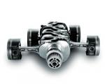
The primary benefits I see for the transaxle are:
- some weight transfer to the rear
- smaller driveshaft tunnel, more foot / pedal room
- no engine / transmission connection problems, use any motor

Downsides:
- New territory, more design work
- transaxle availability and cost ?
- shifter and clutch mechanisms more difficult

There are more items on the above lists ( and I will update the lists if people notice significant omissions ) and some are more complicated or inter-related. For instance reducing / removing most of the transmission and drive tunnel gives a lot more room and also makes the frame much simpler and quicker to build. The strength and stiffness provided by a robust tunnel is gone now though. I think it is better invested in steel outside the passenger compartment for safety. We will need to run this thru "Grape" and see if making the frame taller can replace the stiffness. I don't know, but think so. We should be able to do this part before the year is out.
Marcus Barrow - Car9 an open design community supported sports car for home builders!
SketchUp collection for LocostUSA: "Dream it, Build it, Drive it!"
Car9 Roadster information - models, drawings, resources etc.
User avatar
Glen
Posts: 602
Joined: May 8, 2007, 9:50 am
Location: Minnesota

Re: My messy new shop

Post by Glen »

Have you considered the Subaru transaxle? That would solve your cost/availability issue. Mounting is very similar for anything from a basic FWD 5-spd all the way up to a 6-speed with dog gears, various gearing and LSD options exist, as well as clutch mechanisms and shifter soluluions, the center diff is easy to remove/disable.
User avatar
horizenjob
The voice of reason
Posts: 7652
Joined: January 10, 2008, 4:47 pm
Location: Massachusetts

Re: My messy new shop

Post by horizenjob »

So far as I know the Subaru would be a fine choice. The one issus, and I think it would be shared by the Audi / Passat, is that it can't run upside down. I think that means the driveshaft will be about 6" higher going into the rear bulkhead. This probably isn't a big deal. That's the point of this modeling though. I'll have to pick one of these and make a simple model. It really only needs to be the bolt circle on the face, input shaft and then a rough box for the bulk of the unit.

I think we have pictures and dimensions in one of our threads. So I'll take this as one vote for the Subaru. My other thought has been the Passat, but we already have one person interested in a V8, so also have to look for a robust unit. We can model them up and put them on the shelves, then swap them in and see what they look like.
Marcus Barrow - Car9 an open design community supported sports car for home builders!
SketchUp collection for LocostUSA: "Dream it, Build it, Drive it!"
Car9 Roadster information - models, drawings, resources etc.
User avatar
carguy123
Toyotaphobe
Posts: 4829
Joined: April 5, 2008, 2:25 am
Building: Choppercrosser
Location: Fort Worth, Texas

Re: My messy new shop

Post by carguy123 »

So what if the Subie is 6" high, I'm presuming most people will want a tunnel if for nothing else and arm rest or a place to attach a hand brake.

Now if it means the the punkin sits extra high which forces compromises in suspension geometry that would be a different matter.

I would have sworn I'd read the VW unit could be run upside down, but maybe that's only the old VW stuff and not the newer VW/Audi stuff.

Would either move the flywheel and starter to the rear? To me that would seem to eliminate a few engine placement issues. Of course it opens up the issue of having to design a removable plate so that you could work on it from the top.
mobilito ergo sum
I drive therefore I am

I can explain it to you,
but I can't understand it for you.
User avatar
horizenjob
The voice of reason
Posts: 7652
Joined: January 10, 2008, 4:47 pm
Location: Massachusetts

Re: My messy new shop

Post by horizenjob »

I don't think it changes the suspension geometry. For people that are planning on running 2" of ground clearance you might land up with a lot of angle on the half shafts. I know the Subaru doesn't run upside down. The old VW and Porsches units can run upside down. I don't know yet about the Audi and Passat ones. The unit in the model now is Hewland and it's built into an upside down VW bug case.

Would either move the flywheel and starter to the rear? To me that would seem to eliminate a few engine placement issues. Of course it opens up the issue of having to design a removable plate so that you could work on it from the top.


I am planning on moving the flywheel and clutch. In for a dollar in for a pound or something like that. I'm not sure what you mean by the plate though. I expect this would come out pretty easily though. There is basically no frame behind the roll bar besides the braces and rear hoop. The transaxle should unbolt from the adapter plate and slide rearwards. It's funny we're going to have an adpater plate - to nothing. :)

Honestly, I dream of the day one of our guys wears out a clutch or a starter motor on their locost. :cheers:
Marcus Barrow - Car9 an open design community supported sports car for home builders!
SketchUp collection for LocostUSA: "Dream it, Build it, Drive it!"
Car9 Roadster information - models, drawings, resources etc.
User avatar
horizenjob
The voice of reason
Posts: 7652
Joined: January 10, 2008, 4:47 pm
Location: Massachusetts

Re: My messy new shop

Post by horizenjob »

Still slaving on this stuff. The rear end work has been grueling, keep going over it, trying to get it right, but land up going around in circles. I'm going to take a deep breath and use what I've learned so far and take another shot. Hopefully pictures soon of that work.

Here's some pictures of a Locost chassis side by side with my work. I've been pretty much avoiding this type of thing because I would like my work to be somewhat original, but it makes sense at this point to do some of this just to keep things in context.

I've been trying to keep the wheelbase to the same 92", but am now thinking that something like 95"-96" inches is not unreasonable and might help out. You can see my frame is a good chunk shorter then a Locost, for the same wheelbase.

I didn't get any enthusiastic responses to my comments about the raised floor for aero / ground effects. I'm thinking now that that is making things difficult for me ( go figure! ) and perhaps it makes sense to take a more standard route and try this latter for more advanced work.

Any opinions?

Here's the comparison shots. This is a nice benefit of this Sketchup work - the ability to compare and put different things side by side. I could put up shots of a Caterham chassis side by side too, if anybody thought that would be interesting.
You do not have the required permissions to view the files attached to this post.
Marcus Barrow - Car9 an open design community supported sports car for home builders!
SketchUp collection for LocostUSA: "Dream it, Build it, Drive it!"
Car9 Roadster information - models, drawings, resources etc.
User avatar
oldejack
Posts: 2081
Joined: April 12, 2010, 5:40 pm
Location: san francisco bay area

Re: My messy new shop

Post by oldejack »

Raised floor. .. I've been wondering about the possible value of UHMW strips down the perimeter on a smooth bottom surface the stuff is cheap and you can cut it with whatever you have handy. .
Sure ablative trim is a nice concept (whether it's worth anything or not I won't comment on) but I'm more interested in the aero value. How deep of a skirt would be enough to create a noticeable difference?
I've played with smoothing the under car airflow (pans and such) for improving fuel economy but haven't tried skirts :roll:
"There are times when a broken tool is better than a sound one, or a twisted personality more useful than a whole one.
For instance, a whole beer bottle isn't half the weapon that half a beer bottle is ..." Randall Garrett
User avatar
GonzoRacer
We are Slotus!
Posts: 7651
Joined: October 6, 2009, 9:29 am
Building: Mallock-Locost-V8
Location: Tallahassee, FL (The Center of the Known Universe)

Re: My messy new shop

Post by GonzoRacer »

I didn't get any enthusiastic responses to my comments about the raised floor for aero / ground effects. I'm thinking now that that is making things difficult for me ( go figure! ) and perhaps it makes sense to take a more standard route and try this latter for more advanced work.


Ya know, Marcus, I thought about doing "downforce tunnels" under the sidepods of the Slotus, but didn't, because I was afraid they might work!

What I mean is, supposin' we whip us up some tunnels under the car and we generate downforce... How does one design such things? (I see me sighting over my thumb like an artist in the movies.) How much downforce are we making? How much do we need? What speed range are the tunnels effective? How do we adjust spring rates to optimize the downforce without being too stiff? (or too soft?) It seemed to me that I might create a monster that I couldn't figure out how to use. Either that or they'd generate downforce and suck themselves right off the car as soon as I got it up to about 70 or so. Bad picture...

And that's why the Slotus has a flat bottom... :mrgreen:

I'm likin' your design a lot, Bro... I see several things I wish I'd done on mine... Next time!

JD "May the (Down) Force Be With You" Kemp
JD, father of Quinn, Son of a... Build Log
Quinn the Slotus:Ford 302 Powered, Mallock-Inspired, Tube Frame, Hillclimb Special
"Gonzo and friends: Last night must have been quite a night. Camelot moments, mechanical marvels, Rustoleum launches, flying squirrels, fru-fru tea cuppers, V8 envy, Ensure catch cans -- and it wasn't even a full moon." -- SeattleTom
User avatar
horizenjob
The voice of reason
Posts: 7652
Joined: January 10, 2008, 4:47 pm
Location: Massachusetts

Re: My messy new shop

Post by horizenjob »

Raised floor. .. I've played with smoothing the under car airflow (pans and such) for improving fuel economy but haven't tried skirts


I was avoiding skirts, trying to be a little stealthy, thinking along the lines of sills made from the aluminum sides wrapping under several inches. The sills under the sides would have been maybe 3"-4" wide. The floor was even with the bottom up around the engine firewall bulkhead and was up maybe 3", maybe more, by the rear roll bar.

I think this car will be able to have a smooth floor, at least that's the way it's drawn now.

I'm likin' your design a lot, Bro...

Thanks loads JD! I'm thinking your right and this underbody aero stuff is a complication I can't afford until much later. Will just have to re-visit this when things like attaching the wheels have been accomplished. :)
Marcus Barrow - Car9 an open design community supported sports car for home builders!
SketchUp collection for LocostUSA: "Dream it, Build it, Drive it!"
Car9 Roadster information - models, drawings, resources etc.
User avatar
horizenjob
The voice of reason
Posts: 7652
Joined: January 10, 2008, 4:47 pm
Location: Massachusetts

Re: My messy new shop

Post by horizenjob »

So like I said, I'm struggling thru the rear suspension part of the frame now. I'm half way between a raging cornered animal and a someone in the corner of a dark room drooling and muttering about "his precious"... The whole rear suspension of my antique formula ford is held on with 2 bolts, 4 if you count the trailing arms. I suppose those old cars are more works of genius then I have given them credit for. Having taller uprights with a wide base would be a big help though. I didn't realize how much, but it puts the control arms much closer to where framework naturally is on a little car.

In order to preserve my sanity I had to fork my little project and go down two paths. I was going crazy just moving tubes around and hitting roadblocks, which would turn out to be the same roadblocks I had hit a day or two earlier. So I settled on two approaches and am drawing them both up.

This project is partly inspired by the 2 bolts holding my racecar's suspension on and a picture of Modernbeat's car after he had removed all the frame behind the roll bar. It was a solid rear axle car and still functional.

So I will include a couple of pictures of both approaches in the net two posts with some comments. You folks, my gentle readers, can vote and opine on what you like and dislike about these approaches. They are not done yet and I'm sorry about that.

For lack of better names at the moment I have called them the "rear mini-box" and "rear bulkhead" approach. The "rear bulkhead" approach was what I originally imagined. In my FF the lower control arms bolt to the bottom of the transaxle. Basically the same bolts that hold the transaxle on to the motor adapter. Neither the Miata nor the Thunderbird parts can do that. It also seems difficult to allow easily for different ride heights. I'd like that so that people can build this car they way they would like - street or track etc.

The "rear mini-box" puts a couple vertical ( slanted actually ) pieces of frame out next to the transaxle for the upper and lower arms to bolt to. You can just move the holes if you want to design for a different ride height.

Anyway, I'll take the screenshots now and put them hereafter...
Marcus Barrow - Car9 an open design community supported sports car for home builders!
SketchUp collection for LocostUSA: "Dream it, Build it, Drive it!"
Car9 Roadster information - models, drawings, resources etc.
User avatar
horizenjob
The voice of reason
Posts: 7652
Joined: January 10, 2008, 4:47 pm
Location: Massachusetts

Re: My messy new shop

Post by horizenjob »

Here are a couple pictures of the "minibox" approach. I'm not sure there is anything mini about this, but that's what I came up with at the moment I decided to do both paths.

The tubes being discussed are in red. These pictures are of the side of the car with the Miata upright. The Thunderbird side looks similar and seems to be just as happy. There is room for the coilover on the Miata side, but it's a little funky. Maybe need to go inboard on the rear. I'd like to avoid pivots, so am considering putting a triangle on top of the lower wishbone. We'll see.

The support for the transaxle needs to be strong, just like a diff. When starting in first gear the transaxle will try to tuck down at the rear. So that's why the upper horizontal part looks a bit like a truss beam, it is. I figure you could get a couple of thousand foot pounds pretty easily even with a low power engine, counting the gear reduction and a certain amount of jerking depending on pavement.
You do not have the required permissions to view the files attached to this post.
Marcus Barrow - Car9 an open design community supported sports car for home builders!
SketchUp collection for LocostUSA: "Dream it, Build it, Drive it!"
Car9 Roadster information - models, drawings, resources etc.
User avatar
horizenjob
The voice of reason
Posts: 7652
Joined: January 10, 2008, 4:47 pm
Location: Massachusetts

Re: My messy new shop

Post by horizenjob »

Here is the "rear bulkhead" approach. As I was taking the shot I had a sudden thought that might be fixing up my issues. You know how you go to explain a problem your having and then the answer becomes obvious while your explaining even though you may have worked on it for days?

Well it occurred to me to run a crosswise member where the the wishbones bolt on the formula car and then take the vertical pieces from the other mini box idea and combine things. I think this might work out. We will have to see in the light of day.

In this version the main roll hoop has been moved back 2"-3". That's why we can run this tube behind the bottom of the transaxle and get the suspension to bolt up, since it's a few inches behind the face of the transaxle.

I am ignoring some issues with the starter motor, but the one in this model is not correct anyway, so this will have to be checked.

I know this picture doesn't show things very well. Will do some more cleanup and get better pictures.

After you guys do some voting or heckling or whatever, we will pick a way to go forward and I will update the model in the SketchUp warehouse. There have been many updates.
You do not have the required permissions to view the files attached to this post.
Marcus Barrow - Car9 an open design community supported sports car for home builders!
SketchUp collection for LocostUSA: "Dream it, Build it, Drive it!"
Car9 Roadster information - models, drawings, resources etc.
User avatar
horizenjob
The voice of reason
Posts: 7652
Joined: January 10, 2008, 4:47 pm
Location: Massachusetts

Re: My messy new shop

Post by horizenjob »

Oh crap, this last idea is great, but it permanently welds the transaxle into the car. Oh, well time for bed. Will have to ponder... :rofl:
Marcus Barrow - Car9 an open design community supported sports car for home builders!
SketchUp collection for LocostUSA: "Dream it, Build it, Drive it!"
Car9 Roadster information - models, drawings, resources etc.
User avatar
carguy123
Toyotaphobe
Posts: 4829
Joined: April 5, 2008, 2:25 am
Building: Choppercrosser
Location: Fort Worth, Texas

Re: My messy new shop

Post by carguy123 »

Can you post a pic of how the FF did it?
mobilito ergo sum
I drive therefore I am

I can explain it to you,
but I can't understand it for you.
User avatar
horizenjob
The voice of reason
Posts: 7652
Joined: January 10, 2008, 4:47 pm
Location: Massachusetts

Re: My messy new shop

Post by horizenjob »

Can you post a pic of how the FF did it?


Not very easily. As a relatively non-moving item for the last year and a half, it is now rather buried in the garage. I will try though.

If you go back a page in this thread you will see a picture of a Lotus F1 ( I think ) car. It is the same setup as what I am trying to do. You can see it's so simple.

I will give a description and then see if I can clear some stuff and get a picture this afternoon. At the rear of the car is a cross member connecting the top rails. The transaxle hangs from this with it's ears on the diff endplates. THis same crossmember has ears on it's ends to support the UCA and coilover. At the bottom of the bellhousing are two mounting bolts. These are used to support a small bracket which takes the LCA mounts.
Marcus Barrow - Car9 an open design community supported sports car for home builders!
SketchUp collection for LocostUSA: "Dream it, Build it, Drive it!"
Car9 Roadster information - models, drawings, resources etc.
Post Reply

Who is online

Users browsing this forum: No registered users and 2 guests